
Finite Element Analysis (FEA) is now a regular part of pressure-equipment engineering, particularly when a vessel detail, load path, or failure mode is not well represented by the usual Design-by-Rule equations. The value of FEA is not the contour plot itself. Its value is in showing, with a traceable engineering basis, how a proposed design behaves under the applicable loads and whether the relevant Code acceptance checks have been addressed. This article is based mainly on the practical guidance presented by Trevor Seipp and Mark Stonehouse in ASME PVP2014-28958.
What FEA Drives in Equipment Design
FEA is generally considered when the design question cannot be answered adequately by the available closed-form Code rules, or when a local detail needs a more direct assessment of stress, strain, deformation, stability, or cyclic response. Not every non-standard detail automatically requires FEA, and not every FEA model becomes a Code Design-by-Analysis assessment. The required approach depends on the geometry, loading, Code basis, and the failure mode being evaluated.
Typical situations where FEA may become useful include:
- Non-standard nozzles, reinforcement details, branch connections, or penetrations that are not conveniently covered by the available design equations.
- Local loads from piping, platforms, lugs, clips, supports, lifting attachments, or other external loads that create localized shell or head stresses.
- Complex transitions, flat heads, thick-to-thin junctions, abrupt changes in stiffness, or geometric discontinuities where local stress distribution matters.
- Support regions such as skirts, saddles, legs, support rings, or attachment details where load transfer into the vessel wall needs to be understood.
- External-pressure or compression-dominated situations where buckling or instability may govern.
- Cyclic pressure, thermal cycling, or other repeated loading where fatigue or ratcheting may need to be evaluated.
- Thermal gradients, contact, preload, or other interactions that are difficult to represent using a simple hand calculation.
The analysis can influence practical design decisions such as local wall thickness, reinforcement geometry, transition radii, support arrangement, nozzle spacing, stiffener layout, weld detail, or the allowable load envelope at a nozzle or attachment. In that sense, FEA can become a design tool, not only a final verification step.
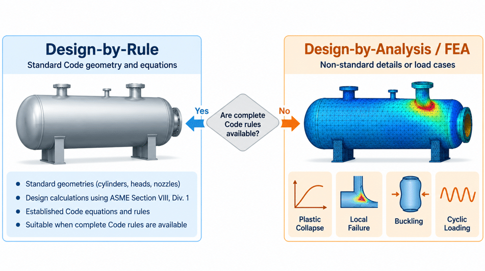
For a Division 1 Vessel, FEA Does Not Replace Existing Division 1 Rules
A useful point from Seipp and Stonehouse is that FEA should not be treated as a way to bypass an existing Division 1 design rule. Where Division 1 provides an applicable rule for the detail being designed, that rule remains part of the construction basis.
Where complete design details are not provided, the paper points to Article U-2(g). In that situation, the Manufacturer is responsible for providing design and construction details intended to be as safe as those covered by the Division, subject to the acceptance required by the Code. An FEA may form part of that engineering justification.
The paper further recommends that, when FEA is used to support a Division 1 vessel, the Design-by-Analysis methodology of Division 2, Part 5 be used where applicable. For an elastic analysis, the authors recommend retaining the Division 1 allowable stresses from Section II, Part D for the applicable product form. The exact application should still be checked against the governing Code edition, project specification, Inspector requirements, and the expectations of the applicable jurisdiction or registration authority.
What Is Design by Analysis (DBA) under ASME Section VIII, Division 2, Part 5
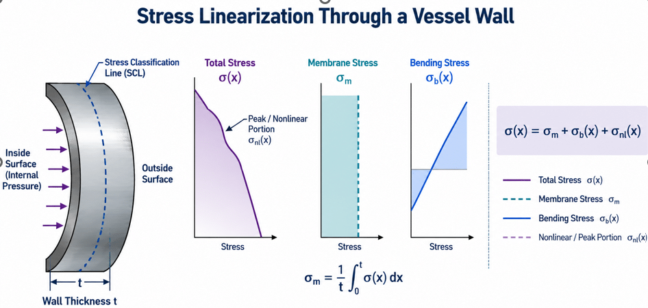
Design by Analysis is a structured way of demonstrating protection against specific failure modes. Instead of asking only whether the maximum plotted stress is below one allowable value, the Part 5 philosophy asks a different question: what failure mechanism is being considered, what analysis method is suitable for that mechanism, and what margin against that failure is required?
In the 2013 edition discussed by Seipp and Stonehouse, the central Part 5 checks are:
- Protection against Plastic Collapse – Part 5.2
- Protection against Local Failure – Part 5.3
- Protection against Buckling – Part 5.4
- Protection against Failure from Cyclic Loading – Part 5.5
Protection against Plastic Collapse – Part 5.2
The objective is to demonstrate that the component has adequate resistance to gross plastic deformation or collapse for the required load combinations. The paper identifies three analysis routes in the cited edition:
- Elastic stress analysis method
- Limit-load method
- Elastic-plastic stress analysis method
The selected route changes how the FEA results are interpreted. For example, an elastic route relies on stress classification and the applicable stress limits, while a limit-load or elastic-plastic route evaluates collapse in a different way. A report should therefore state which route is being used and why it is suitable for the design question.
Protection against Local Failure – Part 5.3
Local failure addresses highly localized material response that may occur even when the component is not approaching gross collapse. The paper identifies elastic and elastic-plastic assessment routes. It also notes that the mesh suitable for plastic-collapse assessment may not necessarily be adequate for local-failure assessment, because local strain and stress gradients can require greater resolution in the critical region.
Protection against Buckling – Part 5.4
Buckling becomes relevant where compressive stress states or external-pressure effects can produce instability. The paper describes several approaches in the cited edition, ranging from bifurcation buckling to nonlinear analysis with geometric nonlinearity and explicit imperfections. The appropriate method depends on the problem being assessed.
One practical review point is model symmetry. Seipp and Stonehouse recommend caution with symmetry models for buckling because a partial model can suppress a non-symmetric mode that would be possible in the full structure. Where buckling is applicable, the model should be capable of representing the relevant mode shapes and the assumptions used should be explained.
Protection against Failure from Cyclic Loading – Part 5.5
Cyclic loading is treated differently from a one-time collapse check. The paper describes fatigue screening followed, where required, by a fatigue assessment using the applicable method. The cited edition includes elastic stress, elastic-plastic strain, and structural-stress approaches for welds. The paper also notes that protection against ratcheting needs to be considered as part of the cyclic-loading evaluation.
The important point is that one attractive stress contour does not address all four failure-mode groups. Different checks may require different result quantities, modelling assumptions, mesh density, or post-processing.
What Should a Good FEA Analysis and Report Contain?
A useful FEA report should connect the entire engineering chain: design basis -> model -> loads and boundary conditions -> numerical results -> Code assessment -> conclusion. If one of those links is missing, the reviewer may be able to see what the software calculated without being able to judge what the calculation means.
Geometry and model assumptions
The model description should identify the geometry being represented, the source drawings, important dimensions, any simplifications, the dimensional idealization used (for example 2D, 3D, axisymmetric, shell, solid, or mixed elements), and how different element types are connected. Simplifications are often reasonable, but their effect on stiffness and load transfer should be explained.
Loads, restraints, contact and load combinations
Pressure, mechanical loads, thermal loads, support reactions, restraints, symmetry conditions, rigid-body controls and contact assumptions should be described in a way that makes the load path understandable. A solver can converge with unrealistic restraints; numerical convergence alone does not establish that the boundary conditions represent the actual vessel.
This is particularly relevant for local submodels. If a short length of shell around a nozzle is cut from the global vessel and the cut boundary is fully fixed, the local region may become artificially stiff. The review question is whether the boundary reproduces the stiffness and load transfer of the structure that has been removed.
Material properties
The paper recommends reporting the numerical material properties actually used in the model, together with their source and temperature dependence where applicable. Identifying only the material specification is not enough to reproduce an analysis. Depending on the model, relevant properties may include Young’s modulus, Poisson’s ratio, coefficient of thermal expansion, thermal properties, density, yield strength, ultimate strength, allowable stress, and the stress-strain curve used for nonlinear analysis.
Stress results need interpretation, not only a maximum value
Suppose an FEA shows a maximum equivalent stress of 420 MPa at a sharp corner while the material allowable stress is much lower. That number may be important, but by itself it does not establish the Code conclusion. The reviewer still needs to know where the stress occurs, what caused it, which failure mode is being checked, whether the location represents a structural discontinuity, and whether a numerical singularity may be present.
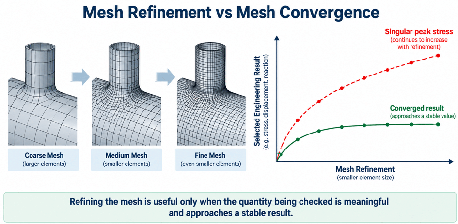
Sharp re-entrant corners, point restraints, idealized contact edges and abrupt load introduction can create stresses that continue to increase as the mesh is refined. That is one reason stress classification and the selected Design-by-Analysis method matter.
Elastic stress analysis and stress linearization
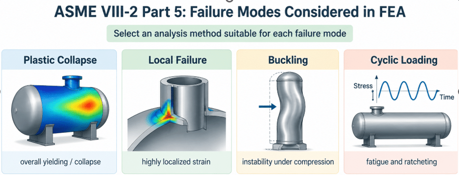
For an elastic stress analysis, a through-thickness stress distribution is commonly separated into membrane, bending and nonlinear components for the applicable assessment:
The Stress Classification Line (SCL) location and the software post-processing method should be documented. Seipp and Stonehouse specifically caution that a software default stress-linearization routine is not automatically equivalent to the Annex 5.A procedure cited in the paper; the analyst should confirm that the chosen implementation is consistent with the applicable Code method.
Conceptual stress linearization through a vessel wall. The applicable Code procedure should govern the actual assessment.
Mesh refinement and convergence
A visually fine mesh is not the same as a demonstrated converged result. The paper recommends describing the mesh size and important local features and treats convergence evidence as good practice, even though it notes that a formal convergence study is not explicitly required for every FEA.
A convergence study should track a quantity that is meaningful for the engineering decision, such as displacement, reaction, a linearized stress quantity, limit load, or another result appropriate to the selected assessment. Tracking the maximum stress at a true singularity can be misleading because the peak may continue to increase as the element size decreases.
A Reviewable FEA Report Should Allow Another Engineer to Reproduce the Analysis
Seipp and Stonehouse propose a practical test of report quality: another competent analyst, using the referenced drawings and documents, should have enough information to independently duplicate the analysis. This is a useful benchmark because it forces the report to expose assumptions that would otherwise remain hidden inside the model file.
In practice, reproducibility means documenting items such as drawing numbers and revisions, Code editions, software and analysis type, model extent, element formulation, mesh size, contact definitions, material properties, applied loads, load combinations, restraint logic, symmetry assumptions, convergence evidence, post-processing method, and the acceptance route used for each applicable failure mode.
The paper also argues for concise reporting. Reproducibility does not mean including every contour plot generated by the solver. The report is more useful when each figure and table supports a specific engineering conclusion.
FEA Report Review Checklist
The following checklist is a practical way to review whether the analysis and documentation are complete enough for technical review. The exact items will vary with the design, analysis method, and Code edition.
| Review Area | What the Reviewer Should Be Able to Confirm | Useful Snapshot / Evidence |
| Design basis and scope | Component, design condition, governing Code edition, reason FEA is being used, analysis type and intended failure-mode checks. | Overall model and problem statement. |
| References | Drawing numbers, revisions, dates, supporting calculations, material data and referenced procedures. | Critical source drawing or geometry callout if useful. |
| Geometry / model | Model extent, critical dimensions, simplifications, element type/order, shell/solid/axisymmetric basis and connections between element types. | Overall geometry and critical sections. |
| Mesh | Global and local element sizes, refinement at radii/discontinuities, elements through thickness where relevant, and convergence evidence. | Mesh overview plus local refinement. |
| Loads | Pressure, external mechanical loads, thermal loads, preload and applicable load combinations. | Loads shown graphically with directions and magnitudes. |
| Boundary conditions | Supports, restraints, symmetry, rigid-body controls, remote boundaries and rationale for the selected constraints. | Restraint and symmetry plot. |
| Contact | Contact pairs, normal/tangential behaviour, friction or separation assumptions where applicable. | Contact-region plot. |
| Materials | Numerical properties used, source, temperature dependence, strength data and nonlinear stress-strain data where applicable. | Table or graph of properties when temperature-dependent. |
| Results | Deformation plus the stress/strain/plasticity/buckling/fatigue outputs that relate to the selected assessment method. | Deformed shape and only the relevant result contours. |
| Stress linearization | SCL locations, orientation, post-processing method and Code-consistent treatment when the elastic route is used. | SCL locations and tabulated linearized results. |
| Code assessment | Failure-mode-by-failure-mode statement of the method used, acceptance basis and result. | Summary table of checks. |
| Conclusion | What has been demonstrated, for which load/design conditions, plus any limitations or required design changes. | Usually no additional plot required. |
A small presentation detail from the paper is also worth keeping: when several contour plots are compared, using the same contour range or intervals makes the comparison easier to interpret. Otherwise, a change in colour may simply reflect a different auto-scaled legend.
Common FEA Report Issues That Should Trigger Questions
The following items do not automatically mean that an analysis is unacceptable. They are signals that the reviewer may need additional explanation, evidence, or clarification before relying on the conclusion:
- A maximum stress value is reported without identifying the location, cause, failure mode, or acceptance method.
- Boundary conditions are shown, but the report does not explain why they represent the actual structure or removed stiffness.
- Material is identified only by specification, while the numerical properties used by the solver are not reported.
- The mesh is described as “fine” without dimensions, local refinement information, or any indication that the selected result is sufficiently mesh-independent.
- Software-default stress linearization is used without confirming that the post-processing is consistent with the applicable Code procedure.
- One model and one mesh are assumed to be suitable for every failure mode without explaining why.
- Symmetry is used in a buckling model without considering whether a non-symmetric critical mode could be suppressed.
- The report contains many plots but does not show how the selected Part 5 assessment procedure was applied.
- Drawing numbers are listed without revision numbers or dates, making it difficult to confirm that the model matches the design being reviewed.
- A nonlinear analysis is presented without enough information on the material model, contact assumptions, load stepping, convergence controls, or the engineering meaning of non-convergence.
The Report Is Part of the Analysis
Writing the report forces the analyst to state assumptions that can otherwise remain hidden inside the model: why geometry was simplified, why a boundary was restrained, why a failure mode was screened out, why a particular material curve was used, and how a numerical result was converted into a Code conclusion.
That is also why an independent technical review can add value. The reviewer is not only checking whether the contours look reasonable. The reviewer is checking the chain from design basis to model, from model to result, and from result to the applicable acceptance criterion.
FEA is useful because it can represent details that are difficult to address with closed-form equations. That flexibility also means the analysis needs a stated Code basis, appropriate failure-mode checks, traceable assumptions, and documentation proportionate to the complexity of the problem.
References
[1] Seipp, T. and Stonehouse, M., “Writing and Reviewing FEA Reports Supporting ASME Section VIII, Division 1 and 2 Designs – Practical Considerations and Recommended Good Practice,” Proceedings of the ASME 2014 Pressure Vessels & Piping Conference, PVP2014-28958, Anaheim, California, 2014.
[2] ASME Boiler and Pressure Vessel Code, Section VIII, Division 1, Rules for Construction of Pressure Vessels. The Seipp-Stonehouse paper cites the 2013 Edition.
[3] ASME Boiler and Pressure Vessel Code, Section VIII, Division 2, Alternative Rules, Part 5 – Design by Analysis Requirements. The Seipp-Stonehouse paper cites the 2013 Edition.
[4] ASME Boiler and Pressure Vessel Code, Section II, Part D, Properties, as applicable to the project Code edition.
[5] API 579-1/ASME FFS-1, Fitness-For-Service. The Seipp-Stonehouse paper cites the 2007 edition in connection with Division 1 elastic-plastic load combinations.
[6] Seipp, T. G., “An Evaluation of the Protection Against Local Failure in ASME Section VIII, Division 2: Finite Element Model Considerations,” ASME PVP2013-98028, ASME Pressure Vessels and Piping Conference, 2013.
Code note: This article summarizes practical concepts from PVP2014-28958 and is not a substitute for the ASME Code. The applicable Code edition, project specification, Inspector requirements, and jurisdictional requirements should be confirmed for each design.
