The global standard method for pressure vessel design has been the “Design-by-Rule” (DBR) methodology governed by popular Boiler and Pressure Vessel Codes like ASME Section VIII, Division 1, AD 2000, PD 5500, EN13445 among others.
Design by Rule (DBR) relies on established formulas and safety margins to size components like cylinders, heads, and nozzles. However, these rules only work if you assume the equipment is symmetrical and the loads are simple enough to be conservatively analysed by formula-based methods.
The equipment takes physical shape to meet these process demands, the resulting geometry often outgrows the simple mold of established rules in the Code. A vessel’s initial sizing is driven by the process engineer (They dictate exactly what the system needs to function).
When a design falls outside the validated scope of standard rules, every major global code provides an “Alternative Design” provision, most famously recognized as ASME Section VIII Division 1’s Paragraph U-2(g) but equally embedded in the core principles of EN 13445, PD 5500, and AD 2000. As, the Code invokes Alternate analysis requirement clause. This clause essentially says if the book doesn’t cover your geometry, you should mathematically prove the design is safe.
It is a common misconception that triggering these clauses mandates an immediate jump to Finite Element Analysis (FEA). These are Alternative Analysis provisions.
They dictate that when the standard rulebook is silent, the engineer is to validate the structural integrity using recognized engineering mechanics. This can be achieved through closed-form analytical calculations (first principles), proof testing, the application of complementary international standards, OR when the geometric complexity outpaces manual mathematics advanced numerical methods like FEA.
Let’s Explore what are some potential cases Designers and Engineers can come across which will require them to search beyond DBR methods laid out in the respective Code.
In day-to-day static and fixed equipment design, we frequently run into scenarios where standard code rules just aren’t enough. Here are a few of the most common, real-world design issues where FEA becomes an absolute necessity.
While the terminology in the examples below leans on ASME Section VIII, Division 1, the underlying physics applies across the board. Because every major “Design by Rule” standard (from EN 13445 to PD 5500) relies on the same basic assumptions of symmetry and uniform loading, they all share the exact same blind spots.

Local Load Analysis of Geometries Outgrowing WRC Limits
We use WRC 537 / 107 for analysing static reactions on pressure boundaries, some of the following examples are:
We all rely on WRC 107 / 537 and sometimes WRC 297 to determine local stresses in the shell at structural discontinuities such as legs, support lugs and clip attachments. This bulletin does not address rectangular attachments to shells of double-curvature, and these charts have strict geometric limits.
If your nozzle is massive compared to the vessel, or if the shell is extremely thin, or if any rectangular attachment like lug, clips, etc., are welded on double curvature components like heads. WRC methods simply do not provide methods to analyse the concerned geometry.
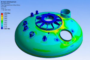
In highly loaded junctions such as a central nozzle supporting an agitator assembly. The standard software with WRC 107 / 537 will provide overstress results and cannot calculate the structural stiffeners. To properly analyze this pressure boundary and guarantee the design is safe, a 3D FEA model is the only practical solution.
Non-Uniform Tubesheets
Standard TEMA and ASME rules for sizing tubesheets rely on one massive assumption: that the plate is uniformly drilled with holes. For tube layouts which are not uniform where tubesheet is perforated for a small region and large part of it is an untubed area, but real-world heat exchangers often require multi-pass flow, which means there is un-tubed metal.
These solid strips act like rigid steel beams. When pressure hits the tubesheet, it doesn’t bend evenly; the un-tubed lanes stay stiff while the drilled areas bow outward. Standard formulas cannot calculate this uneven bending, leading to unexpected shear forces that can rip the tube-to-tubesheet welds apart.
As analysts, we model the exact, true geometry of the tubesheet, including every solid un-tubed lane and irregular perimeter gap. This allows the simulation to capture the exact bending behavior and locate the high localized stresses where the flexible tubed region meets the rigid un-tubed metal, ensuring the welds will hold under operating pressure.
When you introduce unconventional geometries—like massive openings, obround cutouts, offset/tilted nozzles, or nozzles located right on a head knuckle. Per ASME UG-36(a)(1), if the aspect ratio (the long chord divided by the short chord of the opening) exceeds 2.0, the code warns that additional reinforcement is needed to resist complex bending forces.
However, ASME provides no elementary formula for how much reinforcement is needed. Because of this, software will simply flag a permanent warning. This warning will never “disappear” just by artificially thickening the repad in the software, because the error is tied to the physical dimensions of the hole, not the thickness of the steel.
The Large Nozzle Limit: If the nozzle is massive, Appendix 1-7(b) takes over. But even those advanced rules have a ceiling. If the ratio of the nozzle radius to the vessel radius exceeds 0.7, the software will complete the Appendix 1-7 analysis but immediately flag that the geometry is still too extreme, requiring additional analysis per U-2(g).
Pressure vessels aren’t always static. If a vessel undergoes thousands of pressure or temperature cycles over its lifetime (like a batch reactor continuously filling and draining), the metal can eventually crack from fatigue even if the pressure never exceeds the allowable limit. Standard code formulas cannot accurately predict how long this complex geometry will survive under continuous, repetitive stress.
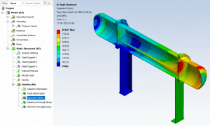
To prove the design is safe, we perform a Fatigue FEA. First, the simulation maps the peak stresses during a single operating cycle. For example, in a recent sump junction analysis, the FEA stress contour pinpointed a maximum stress range concentrated right at the sharp inner corner of the intersection.
We don’t just stop at finding the stress; we have to evaluate the damage. Using ASME Section VIII, Division 2, Part 5 (Clause 5.5.3.2), we take that FEA data and calculate the “effective alternating stress amplitude.“
In other words this code rule helps us measure exactly how much microscopic damage each individual cycle causes. By tallying up this damage using the code’s fatigue curves, we can evaluate fatigue life of the equipment.
Pressure vessel codes are built on the assumption that stress will flow gently through a vessel. However, strict manufacturing constraints, tight footprints, and modern instrumentation frequently force designs entirely outside these comfortable mathematical bounds. Two of the common “out-of-scope” situations are:
The codes take on shape ratios for example, mandating minimum knuckle radii or requiring a smooth 3:1 or 4:1 taper when joining thick metal to thin metal.
But in highly constrained equipment space limitations often force designers to use a much tighter knuckle radius or sharp transitions. Standard formulas cannot calculate the massive stress concentrations that build up in these tight corners.
By generating a 3D mesh of the exact component, we bypass the code’s geometric limits entirely. FEA maps the precise peak stress at the sharp corner, allowing us to mathematically prove simulation evaluates the irregular cutout guaranteeing the integrity of the pressure boundary no matter how odd the geometry is.
Analysts rely on a set of “rules of thumb” to bridge the gap between pure math and practical, code-compliant engineering. Here are seven of the most critical rules used in the trenches today:
How Much to Model?
If you model the entire 100-foot distillation column just to check one nozzle, your computer will take days to solve it. But if you model too little, your boundary conditions will ruin your results.
Stress ripples out from a discontinuity (like a nozzle) and eventually fades away. To capture the full effect,extend your model boundary at least 2.5 (R*t)^1/2 away from the nozzle (where R is the vessel radius and t is the thickness). Also, never apply a completely rigid “Fixed” support to a cut boundary, it prevents the shell from naturally expanding under pressure and creates massive, fake bending stresses.
Mesh Density
In Design-by-Analysis, we are intrigued with how stress bends through the wall thickness. If your mesh is too coarse, the software will literally stiffen the wall and miss the bending gradient entirely.
You should mesh the model in a way that results are mesh insensitive.
Drawing the Line (SCL Placement)
To comply with ASME, the analyst has to extract those colors and split them into Membrane and Bending stresses using a Stress Classification Line (SCL).
Your SCL should be drawn normal (perpendicular) to the mid-surface of the metal thickness.
To Weld or Not to Weld?
Modeling every single weld fillet with a perfectly rounded toe creates a complex mesh.
It depends on what you are checking. If you are just checking for global collapse (Membrane + Bending stress), skip the fillets. Modeling intersections as sharp 90-degree corners is actually slightly conservative and saves hours of work. But, if you are doing a Fatigue Analysis, you should follow code guidelines for fillet welds.
Spotting “Fake” Stresses (The Singularity Check)
In the mathematical world of FEA, a perfectly sharp internal corner will cause the stress to approach infinity. In the real world, the metal just yields a microscopic amount and redistributes the load.
If you see a glowing red hot-spot in a sharp corner, cut your mesh size in half and run it again (Grid Convergence). If the stress stabilizes, it’s a real stress. Singularity check can be performed using mesh independent study. You can usually ignore this peak stress for general collapse checks.
Thermal Properties
For any thermal analysis, you should input the full temperature-dependent curves for the Modulus of Elasticity, Thermal Expansion Coefficient, and Thermal Conductivity straight from ASME Section II, Part D. If you use a constant, flat rate for these properties, your thermal bending stresses will be completely invalid.
Before looking at specific geometries that need FEA, it helps to understand the four main failure modes outlined in Division 2, Part 5.
While the terminology below references the specific failure modes of ASME Section VIII, Division 2, Part 5, the underlying physics does not change. Whether you are proving a design to ASME, EN 13445, PD 5500, or AD 2000, these finite element modeling principles apply universally across all major design codes
We use FEA software like ANSYS or Abaqus to check equipment against these specific criteria:
Protection Against Plastic Collapse
This checks that the vessel won’t yield too much or burst under primary loads like internal pressure and dead weight. The code offers three ways to do this using FEA:
Protection Against Local Failure
Even if the overall vessel is safe from collapse, stiff areas can still fail locally due to high multi-directional tension. FEA is used to check the triaxial stress limits or local plastic strain limits to confirm the material has enough ductility to avoid tearing in these constrained spots.
Protection Against Collapse From Buckling
When vessels face external pressure, vacuum, or heavy compression (like a tall column under wind loads), standard formulas often don’t work for non-standard shapes. FEA evaluates this instability using either simple linear buckling analysis or more detailed elastic-plastic buckling analysis that includes real-world manufacturing imperfections.
Protection Against Failure From Cyclic Loading
A vessel sees repeated pressure changes, thermal shocks, or varying loads, a fatigue assessment is needed. We use FEA to find the peak stresses in the component. By calculating the alternating stress and adding up the fatigue damage over time (using Miner’s Rule), we can verify the equipment will survive its entire design life.
Reaching the limits of standard Design-by-Rule formulas isn’t a roadblock; it’s simply the point where we switch to numerical analysis to get a more accurate picture of the stresses. Knowing when to apply Division 2, Part 5 techniques is a practical skill for solving complex equipment problems. Whether you are dealing with exceeded WRC limits, thermal bending in a support skirt, or the fatigue life of a reactor, FEA gives engineers a reliable way to verify that a design is safe, practical, and code-compliant.
Mr. / Mrs.