
Industrial projects are often described as a sequence: concept, FEED, detailed engineering, procurement, construction and commissioning. That sequence is useful, but it does not fully explain how engineering actually develops. A more practical way to understand an industrial plant project is to follow the information as it moves between disciplines.
A process engineer establishes a flowrate. That flowrate influences equipment capacity. Equipment capacity affects nozzle size, utility demand and electrical load. Equipment dimensions influence plant layout. The layout affects piping routes. Piping flexibility creates nozzle loads. Those loads can then influence equipment supports, structural steel and foundations. The plant therefore develops through a network of dependent decisions.
This becomes particularly important during the transition from Front-End Engineering Design (FEED) to detailed engineering, because assumptions made during FEED can become embedded in specifications, layouts and purchase orders much earlier than expected.
What FEED Is Really Trying to Achieve
Its purpose is to establish enough technical definition for the project team to make informed decisions regarding scope, cost, configuration, site requirements, execution strategy and major technical risks.
Depending on the project, a FEED package may include:
- process design basis;
- heat and material balance;
- process flow diagrams;
- preliminary P&IDs;
- equipment list and datasheets;
- preliminary equipment sizing;
- utility consumption;
- plot plan and equipment arrangement;
- preliminary electrical load information;
- civil and structural concepts;
- cost and schedule information.
One useful way to judge FEED quality is not to ask how many drawings have been issued, but whether the important inputs are mature enough for downstream engineering to use them reliably. A project may have a large drawing register and still have unresolved design-basis information.
Why the Heat and Material Balance Has Such a Large Downstream Effect
The heat and material balance is one of the earliest documents that begins linking process engineering to almost every other discipline.
It establishes information such as:
- flowrates;
- compositions;
- temperatures;
- pressures;
- vapor and liquid fractions;
- heat duties;
- recycle streams;
- utility requirements.
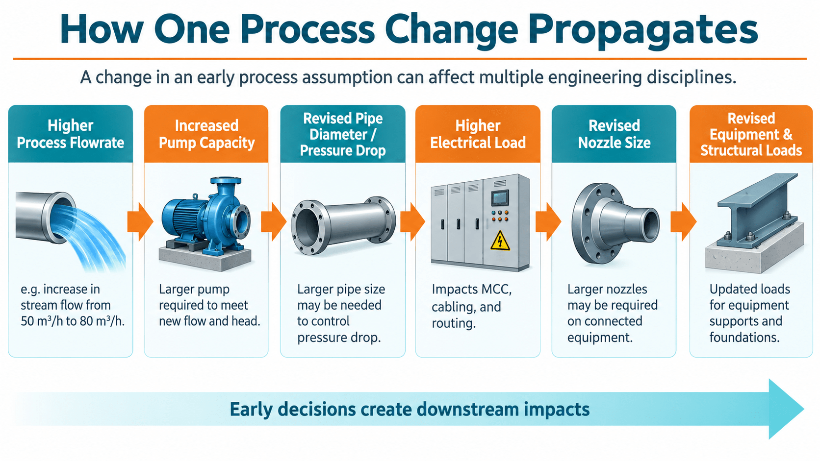
Consider what happens when the design flow through one process train increases. At first, the change may appear to concern only the process simulation. In practice, the chain can extend much further:
Higher Process Flowrate
→ Increased Pump Capacity
→ Revised Pipe Diameter or Pressure Drop
→ Revised Motor Power
→ Higher Electrical Load
→ Revised Nozzle Size
→ Different Piping Route or Support Requirement
→ Revised Equipment and Structural Loads
This is why revisions to a heat and material balance should not be treated as isolated process-document changes. If the revised value has already been used in equipment datasheets, line sizing, electrical load lists or vendor specifications, several downstream documents may need to be revisited.
The Process Stage: PFD and P&ID Engineering Definition
Process Flow Diagram
A PFD generally communicates:
- principal equipment;
- main process streams;
- process sequence;
- significant operating conditions;
- major heat and material flows;
- major utilities.
It explains the process at a system level.
Piping and Instrumentation Diagram
The P&ID develops that process into an operating arrangement. It introduces information such as:
- piping connections;
- valves;
- isolation requirements;
- instruments;
- control loops;
- vents;
- drains;
- relief devices;
- bypasses;
- utility connections.
The distinction matters because a P&ID change often creates physical consequences.
For example, adding a control-valve bypass is not simply the addition of a few symbols.
It may require:
- additional valves and fittings;
- extra piping length;
- additional supports;
- operating access;
- platform access;
- revised pressure-drop calculations;
- more space within the pipe rack or equipment area.
A P&ID therefore sits at an important interface between process intent and physical design.
Process Equipment Sizing
During FEED, process engineers may define a heat exchanger by thermal duty, a pump by flow and head, or a vessel by required process volume.
These values define what the equipment needs to accomplish. They do not yet define the complete mechanical design. Consider a shell-and-tube heat exchanger.
The process or thermal design may establish:
- heat duty;
- inlet and outlet temperatures;
- allowable pressure drop;
- required heat-transfer area;
- fluid allocation.
The equipment design then needs to address another set of variables:
- shell diameter;
- tube size and length;
- tube count;
- tubesheet arrangement;
- shell-side and tube-side design pressures;
- design temperatures;
- materials;
- corrosion allowance;
- nozzle sizes;
- supports;
- thermal expansion;
- maintenance and bundle-removal requirements.
Mechanical design then evaluates whether the selected configuration can withstand the applicable loads and satisfy the governing construction rules.
This separation between process requirement and mechanical adequacy is fundamental.
A process datasheet defines the required operating function. The mechanical design translates that requirement into equipment that can be fabricated, supported, inspected and operated.
Plant Layout Is a Multidisciplinary Engineering Activity
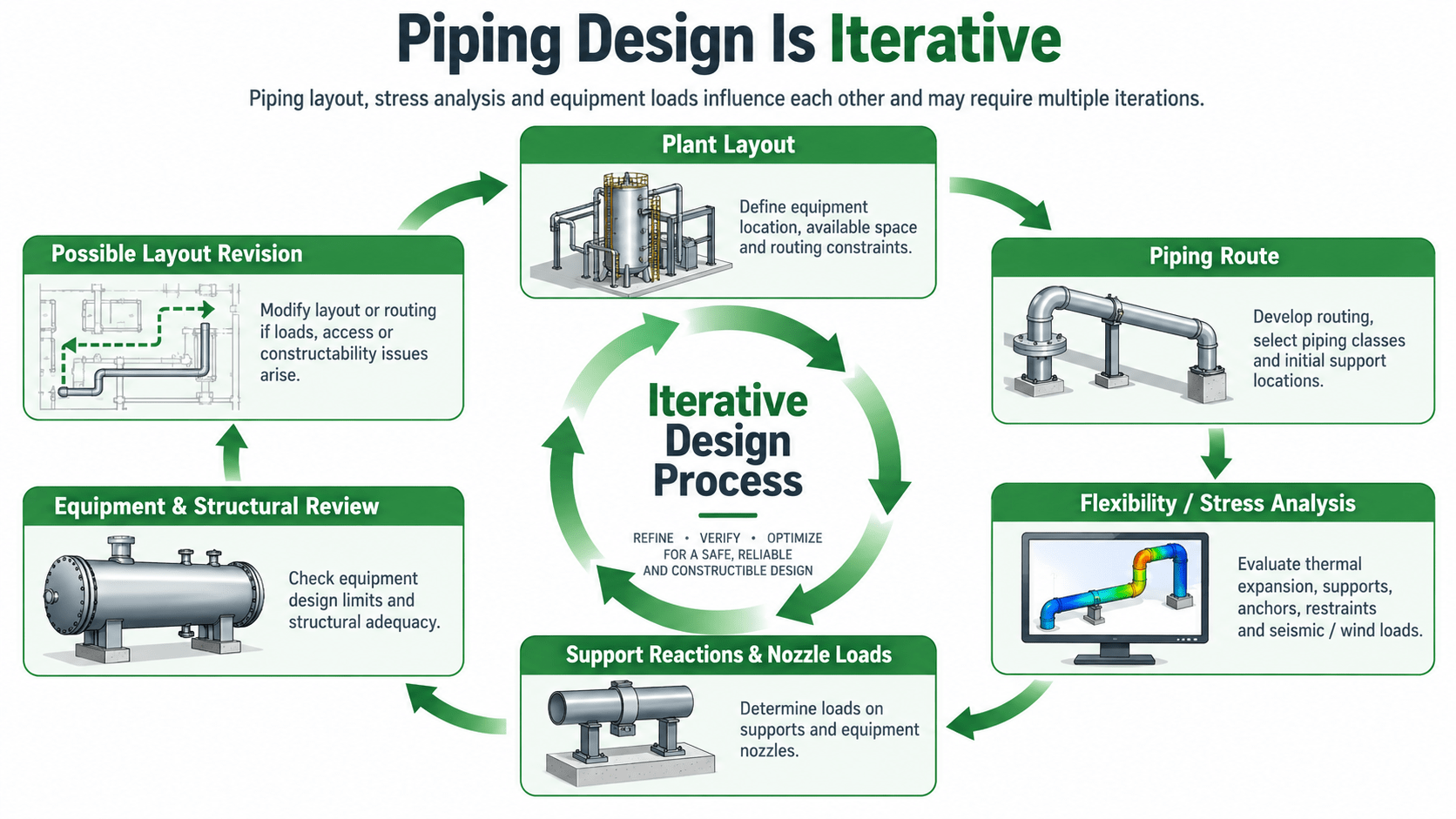
Plant layout is sometimes viewed as a drafting or 3D-model development exercise. In practice, it is an engineering decision-making activity involving several competing requirements. A workable arrangement has to consider:
- operating access;
- maintenance access;
- equipment removal;
- piping routes;
- structural framing;
- lifting requirements;
- instrumentation access;
- electrical routing;
- utilities;
- roads and transportation;
- emergency access;
- future modifications.
A horizontal shell-and-tube heat exchanger is a useful example. The exchanger may physically fit within the allocated plot area, but that does not necessarily mean the arrangement is workable.
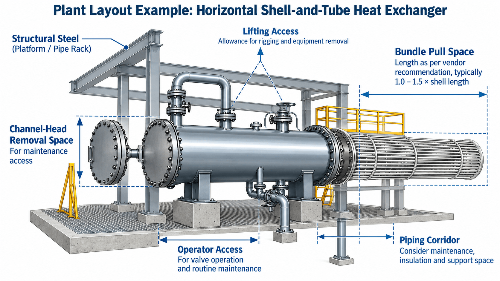
The designer may also need space for:
- channel-head removal;
- tube-bundle withdrawal;
- lifting equipment;
- maintenance personnel;
- pipe disconnection;
- instrument access.
If bundle-removal space is discovered late, nearby piping, steelwork and equipment may require revision.
The equipment footprint is therefore only one part of the real maintenance envelope.
Mechanical Equipment end up as Structural Loadings
Every equipment selection ultimately produces loads that another discipline has to support.
A vertical pressure vessel, for example, can generate:
- empty weight;
- operating weight;
- test weight;
- wind load;
- seismic load;
- piping loads;
- platform loads;
- insulation weight.
Piping similarly creates:
- vertical reactions;
- anchor forces;
- guide loads;
- thermal reactions;
- occasional loads.
This creates another important information interface. Structural design often begins before final vendor loads are available. Preliminary values may therefore be used during early design.
That is reasonable provided the project distinguishes between Preliminary Design Loads and Final or Certified Vendor Loads. The concern is not using preliminary loads. The concern is allowing a preliminary assumption to remain in the final design after the equipment data has changed. A useful project-control practice is to maintain a load register showing the source, revision and status of equipment and piping loads used for structural design.
(VDR) Vendor Data Review Is Part of Detailed Engineering
Procurement does not end engineering involvement. Once equipment is purchased, vendor drawings become a new source of design information.
A vendor package may introduce changes to:
- nozzle orientation;
- nozzle size;
- baseplate dimensions;
- equipment weight;
- center of gravity;
- motor rating;
- electrical characteristics;
- utility consumption;
- maintenance envelope;
- support arrangement.
Each change may need to be incorporated into the plant model and supporting calculations. For this reason, vendor-document review should examine interfaces rather than only confirming process performance.
A pump may satisfy the required flow and head while still creating design issues if:
- the nozzle orientation conflicts with the piping route;
- the motor rating differs from the electrical load list;
- the package weight exceeds the structural design basis;
- maintenance clearance conflicts with nearby equipment;
- materials do not match the project specification.
Vendor review is therefore one of the points where FEED assumptions meet actual purchased equipment.
Commissioning Tests
Mechanical completion does not necessarily mean the system performs as intended. Commissioning provides a structured way of confirming whether installed systems meet their intended operating requirements. A plant may be mechanically complete while still having:
- incorrect control logic;
- instrument calibration issues;
- valve-position problems;
- equipment operating outside its intended range;
- unresolved deficiencies;
- incomplete operating documentation.
Commissioning therefore closes the loop between the original design basis and the installed plant.
Engineering Process
The individual disciplines of an industrial project are well established. The more difficult problems often occur where information passes from one discipline to another. The engineering process can therefore be represented as:
Process Basis
↓
Heat & Material Balance / PFD
↓
Equipment Sizing / P&ID
↓
Equipment Design / Plant Layout
↓
Piping / Utilities / Electrical / Instrumentation
↓
Structural and Civil Design
↓
Vendor Data / Detailed Engineering
↓
Construction
↓
Commissioning

The important issue is whether a change made in one discipline reaches every downstream activity that depends on it. That is why document control, interdisciplinary checking, revision management and design-basis control are engineering activities rather than administrative tasks.
