
The Role of Pressure Vessels in Oil & Gas: Storage, Processing & Safety

The Role of Pressure Vessels in Oil & Gas: Storage, Processing & Safety Home / Learning Introduction The oil and gas industry relies on pressure vessel to store, process, and transport fluids under high pressure and temperature conditions. These vessels are crucial for refining crude oil, storing natural gas, and ensuring safe and efficient operations. Designed for extreme conditions, pressure vessels play a key role in maintaining operational safety and meeting regulatory compliance. What Are Pressure Vessels? Pressure vessels are specially designed containers that store gases or liquids under pressures higher or lower than atmospheric pressure. Made from high-strength materials like carbon steel, stainless steel, and corrosion-resistant alloys, these vessels must meet stringent industry codes such as ASME Boiler and Pressure Vessel Code (BPVC) and API standards. Key Applications of Pressure Vessels in the Oil & Gas Industry 1. Storage of Gases and Liquids Pressure vessels are essential for safely storing pressurized hydrocarbons like LPG, LNG, hydrogen, and compressed natural gas (CNG). These vessels prevent leaks, enhance environmental safety, and ensure efficient hydrocarbon handling. 2. Separation Processes In extraction and refining, raw hydrocarbons contain a mixture of gases, liquids, and solids. Two-phase and three-phase separators,-types of pressure vessels, help efficiently separate crude oil, natural gas, and water, improving processing efficiency. 3. Heat Exchangers for Thermal Efficiency Shell-and-tube heat exchangers, a type of pressure vessel, regulate temperatures by transferring heat between different fluids. They are widely used in crude oil distillation, LNG processing, and other temperature-sensitive processes. 4. Chemical Reactors for Oil Refining Pressure vessel reactors are used in refining processes like hydrocracking, catalytic cracking, and hydrotreating. These vessels enable chemical reactions that convert crude oil into high-value products like gasoline, diesel, and jet fuel. 5. Boilers and Steam Generation Industrial boilers and steam drums generate steam for petrochemical plants, offshore platforms, and refineries. Steam is critical in power generation and enhanced oil recovery (EOR) methods like steam-assisted oil recovery (SAOR). 6. Transportation of Pressurized Fluids For safe transportation of pressurized gases and liquids, specialized vessels are used for CNG, LPG, hydrogen, and ammonia. These vessels ensure structural integrity and prevent pressure fluctuations during transit. Safety and Compliance in Pressure Vessel Operations Since pressure vessel failures can lead to catastrophic consequences, strict compliance with safety regulations is essential. Industry standards such as ASME Section VIII, API 510, and rigorous non-destructive testing (NDT) methods help prevent failures. Regular inspections, pressure tests, and advanced monitoring systems enhance operational safety. Conclusion Pressure vessels are indispensable in the oil and gas industry for efficient storage, processing, and transportation of hydrocarbons. With advancements in materials, automation, and real-time monitoring, modern pressure vessel technology continues to enhance efficiency and safety. Investing in high-quality, well-maintained pressure vessels ensures long-term reliability and regulatory compliance, supporting the industry’s drive for sustainability and operational excellence.
Optimizing Industrial Projects Through High-Quality Detailed Engineering

Optimizing Industrial Projects Through High-Quality Detailed Engineering Home / Learning In industrial projects, success depends on precise planning, accuracy, and efficiency. Detailed engineering transforms conceptual designs into executable plans, ensuring every component is meticulously designed before construction begins. Detailed engineering design involves creating error-free technical drawings, calculations, and documentation, including 3D models. These models serve as conceptual plans for construction and implementation. The process includes defining equipment, materials, layouts, and operational details to ensure accurate execution. Additionally, these models allow for virtual walkthroughs to identify and resolve any clashes or interferences, helping to test and refine the system’s performance before actual construction begins. By focusing on these critical areas, a quality detailed engineering enhances project efficiency, reduces risks, and ensures smooth execution across industries Piping Systems: Ensuring Seamless Flow Piping engineering plays a vital role in every industrial project, dealing with fluid transport, such as oil & gas, power plants, water treatment, manufacturing, and chemical processing. It focuses on the layout, material selection, and analysis of pipelines to ensure safe and efficient transport of liquids and gases. Key aspects of piping engineering include: Stress analysis to prevent pipe failures Material selection based on operating conditions 3D modeling & routing to optimize space utilization Compliance with ASME B31, API 570, and other industry standards Well-designed piping systems reduce operational risks and improve plant efficiency. 2. Equipment and Pressure Vessels: Enhancing Performance Equipment and pressure vessels play a crucial role in industries like oil & gas, power plants, chemical processing, and manufacturing. Industrial projects involve various equipment and pressure vessels that handle high-pressure and high-temperature processes. Engineering in this area ensures these components are designed, fabricated, and installed correctly to prevent failures and improve performance. Key considerations include: Design & Material Selection: Suitable materials selection like carbon steel, stainless steel, and alloys to withstand high pressure and temperature. Types of Pressure Vessels: Includes boilers, storage tanks, reactors, and heat exchangers, each serving different industrial needs. Safety & Performance: Designed with reinforcements, pressure relief valves, and temperature control systems to prevent failures. Fabrication & Installation: Built using advanced welding, forming, and inspection techniques to ensure durability. Inspection & Maintenance: Regular testing (hydrostatic, ultrasonic, and NDT) to detect leaks, corrosion, or cracks and ensure long-term safety. Proper design and detailed engineering of Pressure vessels and industrial equipment ensures required performance, safety, and reliability, ensuring smooth and efficient operations across various industries. 3. Civil and Structural Design: Building a Strong Foundation Civil and structural design is essential for constructing safe, durable, and efficient industrial structures. It focuses on creating strong foundations and frameworks that can withstand environmental forces and heavy loads Important aspects include: Foundation Design: Ensures stability by selecting the right type (shallow or deep foundation) based on soil conditions and load requirements. Structural Framework: Uses materials like concrete, steel, and wood to create strong infrastructure. Load Calculation: Engineers analyze live loads and dead loads. Seismic & Wind Resistance: Designs must withstand earthquakes, high winds, and other natural forces. Material Selection: Choosing durable, cost-effective, and sustainable materials for long-term performance. A well-planned civil and structural design ensures safety, stability, and longevity, creating structures that support industries for years to come. 4. Electrical Systems: Powering Operations Electrical systems are essential for powering industries, buildings, and infrastructure. They supply and distribute electricity to run machines, lighting, communication systems, and other critical operations. Key areas include: Power Generation: Electricity is produced from sources like thermal, hydro, solar, and wind energy. Transmission & Distribution: High-voltage power lines transport electricity from power plants to substations and then to homes and industries. Transformers: Step-up or step-down voltage to ensure safe power delivery. Switchgear & Circuit Breakers: Protect systems from overloads and short circuits. Wiring & Cabling: Distributes electricity within buildings and industrial plants. Control Panels & Automation: Monitor and regulate electrical operations efficiently Importance of Electrical Systems Continuous Power Supply: Ensures smooth industrial and commercial operations. Safety & Protection: Prevents electrical hazards through grounding, insulation, and protective devices. Energy Efficiency: Smart grids and automation optimize power usage, reducing costs Proper electrical design minimizes power failures, enhances safety, and improves overall efficiency. 5. Instrumentation and Controls: Enhancing Automation Modern industries rely on automation and monitoring systems to maintain efficiency and safety. This field focuses on integrating sensors, control systems, and automation technologies to optimize operations. Key aspects include: Sensors & Transmitters: Measure temperature, pressure, flow, and level to provide real-time data. Controllers: Devices like PLCs (Programmable Logic Controllers) and DCS (Distributed Control Systems) automate processes by adjusting equipment based on sensor inputs. Actuators & Valves: Convert signals into mechanical actions, such as opening or closing valves to regulate flow. SCADA & HMI Systems: SCADA (Supervisory Control and Data Acquisition) and HMI (Human-Machine Interface) allow operators to monitor and control processes remotely. Safety Systems: Alarms and emergency shutdowns prevent failures and accidents. Benefits of Automation in Industries Improves accuracy and consistency. Reduces human error and labor costs. Enhances safety and process control. Increases production efficiency. A well-structured automation system improves precision, reduces human error, and enhances productivity. Final Thoughts: The Power of Detailed Engineering Quality and Precision in Detailed engineering is the foundation of successful industrial projects. By addressing critical areas such as piping, equipment, structures, electrical systems, and automation, it ensures efficiency, safety, and cost-effectiveness. A well-executed plan minimizes risks, enhances performance, and lays the groundwork for long-term industrial success. Whether in oil & gas, power, or manufacturing, partnering with MECS Engineering for detailed engineering solutions leads to seamless project execution, enhanced reliability, and sustainable operation.
Importance of Optimal Piping Layout for Efficient Stress Analysis in High-Temperature Lines
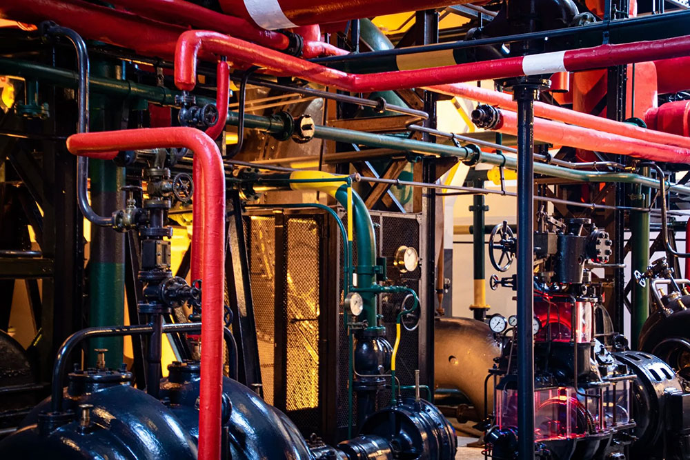
Importance of Optimal Piping Layout for Efficient Stress Analysis in High-Temperature Lines Home / Learning In industries such as oil and gas, chemical processing, and power generation, high-temperature piping systems play a crucial role in ensuring the safe and efficient transportation of fluids. However, designing these systems requires meticulous attention to thermal expansion, stress analysis, and layout considerations. A poorly designed piping layout can lead to serious issues such as excessive stresses, mechanical failures, and even system shutdowns. The optimal piping layout, especially in high-temperature lines, is essential for reducing stress, prolonging equipment life, and ensuring operational safety. Challenges of High-Temperature Piping Systems High-temperature environments introduce an additional layer of complexity to piping systems. In such conditions, metal pipes expand when exposed to heat, which, if not accounted for, can lead to significant stress-related problems like pipe rupture, material fatigue, misalignment of connected equipment and Catastrophic failures. This is where thermal expansion becomes critical. Without accounting for the temperature variations and resulting stresses, the piping system could face catastrophic failures. A well-designed piping layout is essential to managing these stresses and ensuring long-term operational stability. Stress Analysis in Piping Systems Stress analysis is the process of evaluating how various forces act on a piping system, particularly under conditions of high temperature, pressure, and external loads. In high-temperature systems, the primary source of stress is thermal expansion. When thermal expansion is restrained by supports, anchors, or adjacent equipment, it creates internal forces, leading to thermal stress. Thermal Expansion and Its Impact on Piping Systems In high-temperature systems, one of the most critical factors affecting the design and operation of the piping system is thermal expansion. As temperature increases, materials expand—a natural physical phenomenon. Conversely, in cryogenic services, materials contract as temperature decreases. This expansion or contraction can induce significant mechanical stress, especially in long pipe runs, if not adequately accounted for in the layout. Formula for Linear Thermal Expansion: The formula that describes this expansion is as follows: Δx=α×L×ΔT Where: Δx is the change in length (expansion or contraction) α is the thermal coefficient of linear expansion (a material-specific property), L is the original length of the pipe, ΔT is the change in temperature. Even small temperature increases can cause significant expansion over long piping runs, creating stress at joints, supports, and equipment connections. Therefore, understanding and managing thermal expansion is crucial to preventing excessive stress in the system. Thermal Expansion and Piping Layout The poorly planned layouts can magnify the effects of thermal expansion. For instance, a straight run of pipe with minimal support or anchorage may be more prone to thermal stresses, leading to issues such as: Cracking in the pipe material or welds, Leaks at joints due to excessive movement, Bowing or sagging in unsupported pipe sections, Damage to surrounding support structures and misalignment of equipment. How Optimal Piping Layout Reduces Stress in High-Temperature Lines Designing an effective piping layout in high-temperature applications can drastically reduce stress within the system. Here are key layout considerations for mitigating thermal expansion-related stress: Strategic Placement of Supports and Anchors: Supports and anchors serve as the backbone of a piping system, controlling movement and maintaining alignment. However, improper placement can lead to localized stress concentration. A carefully planned layout ensures: Supports: Positioned to allow pipes to expand and contract freely, avoiding sagging or bowing. Fixed supports should be limited to prevent thermal stress accumulation. Anchors: These should be placed where pipes must be restrained, yet positioned to limit stress transfer to sensitive equipment such as turbines or pumps. By using flexible guides, lateral movement can be accommodated while constraining vertical displacement, reducing stress at key points. Use of Expansion Loops : Expansion loops are critical in absorbing thermal expansion without transferring stress to the entire system. By incorporating loops or offsets in the piping layout, the pipe is free to expand and contract naturally, reducing stress concentrations. Expansion loops come in two main configurations: Horizontal Expansion Loops: These are common in long, straight piping runs, providing flexibility that reduces the risk of buckling or deformation. Vertical Loops: Effective in systems with vertical piping runs, although care must be taken to avoid drainage issues or vapor pockets. Rerouting the Pipe: Straight runs of piping are particularly prone to high thermal stresses since expansion occurs in one direction. Introducing bends and elbows into the piping layout allows expansion to be distributed more evenly across the system, reducing stress on any single component. This rerouting process makes the system inherently more flexible and better able to absorb thermal movements. Incorporating Flexible Components: In high-temperature systems, flexible components like bellows, sliding supports, and expansion joints are essential. These components absorb axial movement caused by thermal expansion, allowing the piping to move without inducing stress. However, they require precise design and maintenance to ensure they can withstand operational conditions like temperature, pressure, and flow. Key Factors in Stress Analysis for Piping Layout While optimizing the piping layout, detailed stress analysis is critical to evaluate the design’s adequacy under operational conditions. Key factors in this analysis include: Temperature Differential (ΔT): A large ΔT results in significant thermal expansion, and the system must be designed to accommodate these movements. Material Selection: Different materials have varying thermal expansion coefficients. Selecting materials suitable for the system’s operating temperature is crucial. Code Compliance: Following ASME guidelines ensures the system meets safety standards. Simplified formulas can indicate whether detailed stress analysis, using tools like CAESAR II®, is necessary. Branching and Complex Layouts: Piping systems with multiple branches or varied pipe sizes require individual evaluation of each section to ensure they can withstand thermal stresses. Benefits of an Optimized Piping Layout in Stress Analysis The piping layout directly supports stress analysis by reducing the likelihood of excessive stress buildup and improving system reliability. Here’s how: Minimizes Excessive Stress: A well-designed layout with flexible loops like C or S shapes prevents excessive strain caused by expansion and contraction. Stress analysis using tools like
Piping Engineering: Design, Analysis, and Compliance
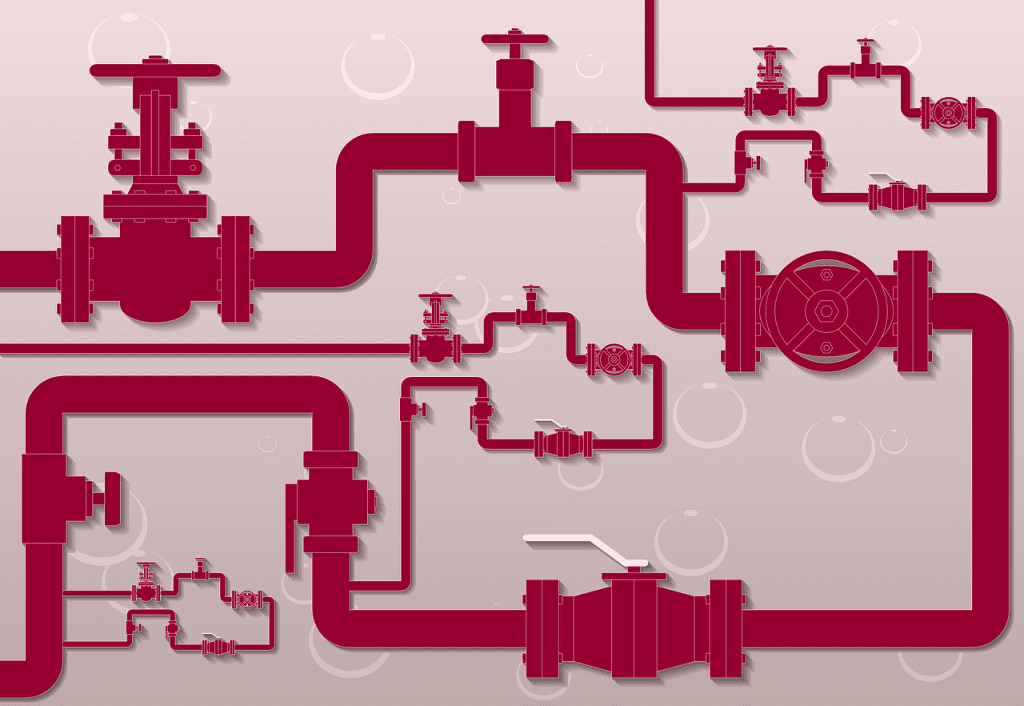
Piping Engineering: Design, Analysis, and Compliance Home / Learning Piping systems, are integral to numerous industrial processes, used to transport fluids between different locations. These systems are composed of various components, including pipes, fittings, and valves, all assembled and designed to ensure efficient and safe fluid transport. Piping engineering is the discipline that integrates material and mechanical engineering principles with specialized techniques like stress analysis and piping layout design. This comprehensive approach converts process documents, such as Piping & Instrumentation Diagrams (P&IDs) and Process Flow Diagrams (PFDs), into detailed piping drawings and data, which guide the procurement, assembly, and testing of piping systems. The Crucial Role of Piping Design The design phase of piping engineering is critical, involving the creation of plot plans, equipment layouts, and three-dimensional (3D) models that define the physical layout of the piping system. Plot Plan Development: It is a top-level drawing showing the entire facility, including equipment, buildings, and structures. It is important to ensure that site constraints, safety, and operational efficiency are considered. Proper spacing between hazardous areas, clear access routes for maintenance and emergencies, and optimal equipment positioning are key factors that contribute to reducing pipeline lengths and enhancing workflow. Equipment Layout: Detailing the position of equipment like pumps, compressors, and tanks within the plot plan is essential. Engineers ensure adequate spacing for maintenance, proper alignment to optimize fluid flow, and the inclusion of support structures for stability and accessibility. 3D Modeling Software: Advanced software tools like AutoCAD Plant 3D and PDMS allow engineers to create virtual representations of piping systems. These 3D models enable the visualization of the entire network, identification of potential clashes, and simulation of fluid flow dynamics, leading to accurate and efficient design. From these models, detailed isometric drawings and material take-offs can be generated. Piping Route and Support Design: The design of efficient piping routes minimizes pressure drops and meets process requirements. Proper support and anchoring systems are critical for managing thermal expansion, vibration, and weight, preventing sagging and stress on connections. Piping Stress Analysis to Prevent Operational Failure Piping stress analysis is a vital process that ensures the safety, reliability, and efficiency of piping systems. The analysis is the study of stresses in a piping system. It is a term applied to calculations, which addresses the static and dynamic loads such as dead weight (self-weight of the pipe including fluid, fittings and its associated components), internal and external pressure, thermal loads (due to change in temperature), seismic loads, wind loads, vibration, water hammer, stream hammer, slug force, PSV reaction force, etc. to produce a comprehensive analysis report. This process is essential to ensure that piping systems can withstand various loads during operation without compromising their structural integrity. Types of Loads in Piping Systems Piping systems are subject to several types of loads, each contributing to the overall stress experienced by the pipes: Ensuring Structural Integrity: Stress analysis evaluates the effects of thermal expansion, contraction, and other loadings on the piping system. By understanding the stress distribution and potential failure points, engineers can design piping systems that maintain structural integrity under extreme conditions. Preventing Overstress: High-temperature environments can lead to overstress in piping components, supports, and connected equipment. Stress analysis helps in optimizing the design to prevent overstress and reduce the likelihood of failures, such as cracking or rupture. Compliance with Codes and Standards: Piping systems must comply with various industry codes and standards, which specify allowable stress values, material requirements, and design considerations. Stress analysis ensures that the piping system meets these requirements, particularly in high-temperature applications where allowable stress values are reduced. Optimizing Design: While ensuring safety is paramount, overdesign can lead to unnecessary costs and inefficiencies. Stress analysis allows for the optimization of piping systems by accurately predicting stress levels and enabling the use of appropriate materials and supports without excessive safety factors. Conducting Piping Stress Analysis Piping stress analysis involves creating a detailed model of the piping system and simulating the various loads it will encounter during operation using specialized software tools. Specialized Software Tools: Engineers use software like CAESAR II, AutoPIPE, ROHR2, and PIPESTRESS to perform both static and dynamic stress analysis, model piping systems, and analyze flexibility and stress under different loads. Modeling the Piping System: The initial step involves developing a detailed model that includes all relevant components—pipes, fittings, valves, supports, and equipment connections. Key aspects are as follows:: Geometry: Accurate representation of the piping layout, including lengths, diameters, and routing. Material Properties: Incorporating the mechanical properties of the piping materials, such as Young’s modulus, Poisson’s ratio, thermal expansion coefficients, and yield strength. Boundary Conditions: Defining the constraints and supports, such as fixed supports, sliding supports, and anchors. Simulating Loads: Engineers simulate various loads, including internal pressure, thermal expansion, weight loads, external forces, and dynamic loads, to assess how the piping system will respond during operation. Internal Pressure: Simulations assess hoop, longitudinal, and radial stresses to ensure the pipe can withstand internal fluid pressure without failure. Thermal Expansion: Temperature changes cause pipes to expand or contract, with simulations helping to design expansion joints and supports that prevent stress-related issues Weight Loads: Engineers simulate the combined weight of the pipe, fluid, and insulation to ensure the support system prevents sagging or overstressing. External Forces: Simulations consider wind, seismic activity, and soil pressure to design supports and bracing that protect the system from external environmental stresses. Dynamic Loads: Transient conditions like water hammer or pump startup/shutdown are simulated to assess the system’s ability to handle sudden changes in flow or pressure. Assessing the System’s Response: The system’s response to loads is evaluated by checking for excessive deformation, comparing stress levels to code limits, and conducting fatigue analysis to identify potential failure from cyclic loading. Identifying and Mitigating Issues: If analysis reveals issues like overstress or excessive deformation, engineers take corrective actions as followed:4 Re-routing Piping: Modifying the layout to reduce stress concentrations and improve flexibility. Adding Supports: Introducing additional supports or changing the type of supports to better manage the loads. Using Expansion Joints: Incorporating expansion joints or loops to
Design Basis: Why is it so crucial to have a well-defined Design basis document for a successful Project

Design Basis: Why is it so crucial to have a well-defined Design basis document for a successful Project Home / Learning We recently finished a project at MECS Engineering that reminded me of the importance of a transparent & well-defined design basis, a topic very close to my heart which I always talk over when I see a gap and hence this article. Before starting any project, a critical and vital element is a well-defined design basis (also called design requirements or basis of design) in addition to a well-defined scope of work (SOW). If not appropriately defined and documented, it results in scope changes, delay in the project timeline, impact on the project budget, and sometimes a total disaster. A concise and complete design basis document makes the basis of a quality design product and a successful project. What is Design Basis? Design basis documents the rationale, criteria, principles, assumptions, and constraints used for detailed engineering and the final design product. It is essentially a set of conditions, requirements, needs of the project & performance criteria, including the legal and code requirements. It applies to an SSC (system, structure, and component) of the complete facility or a modification in the existing facility. This article focuses on the engineering world, although the Design basis importance applies to almost every industry. Various formats are followed by different organizations based on the type of industry. Sometimes it can be an extensive document covering every aspect of the project, from the initiation phase to the installation and commissioning phase, including the commissioning requirements. A caveat, though, is that one should not go into fine details, e.g., detailed calculations, construction details, etc. A project can also fail if the design basis document includes details meant to be part of the detailed engineering. These details are issued as separate documents. If needed, there can be multiple design basis documents, e.g., a separate DB for Piping Design or Structural Design, where specific requirements can be added. U.S. Department of Energy defines Design basis as “Information that identifies the specific functions to be performed by a structure, system, or component of a facility, and the specific values or range of values chosen for controlling parameters as reference bounds of Design. These values may be (1) restraints derived from generally accepted “state of the art” practices for achieving functional goals, or (2) requirements derived from analyses (based on calculations and/or experiments) of the effects of a postulated accident for which a structure, system, or component must meet its functional goals.” What stage Design Basis document should be initiated in project life cycle? The Design Basis document is a dynamic document that can be updated as the project progresses. Typically, it starts at the definition or conceptual / feasibility stage of the project, focusing on the needs and assumptions to meet the project requirements, defining a narrative of the system description like the purpose of the system (or a modification) to meet the specified requirements. The design basis should also address the Constructability, Operability, Maintainability, and Safety (COMS) aspects. It is a crucial part and, if neglected, can even result in the project’s cancellation during the execution stage. I have seen a couple of such cases. Every single component and line in the proposed design should have a thought process supporting it. Most of the requirements, assumptions, and constraints should be captured during the conceptual phase; however, additional details may be needed during the preliminary stage, which should be added when known and the document revised. By the end of the Preliminary engineering phase, the Design Basis document should be rock solid with all required information for the detailed engineering. Any significant change during the detailed engineering phase would impact the project timeline, budget, and sometimes a total disaster. What is covered in the design basis document? Depending on the project’s scope (minor OR major modification OR an entirely new facility), industry type, the design base document varies in detail. Nevertheless, the goal is to have all the required information as described above so that an independent team can deliver a final product without coming back to the author of the Design Basis document for any clarification (Ideal case). Here is a generic partial list of information typically included in the DB. Project Requirements (Project need statement) Scope of the Project Relevant Legislation: Licensing and Registration requirements Applicable Codes and Standards QA requirements Operational conditions and limits (Normal operating conditions, anticipated operational occurrences) Design Parameters and Loads: Pressure, Temperature, Thermal, Seismic, wind, snow, Environmental conditions and requirements Ambient conditions Safety Requirements Human factors requirements Material specifications and factors affecting the material selection e.g., corrosion, erosion, neutron flux in the nuclear facility Interfacing systems: The life expectancy of the installation Assumptions considered in the design Limitations on the Design Constraints: Site access, material selection or material movement, or any such constraint Testing requirements Commissioning requirements (at high level) Additional parameters in specific cases: Certain projects need special attention to the complete cycle of the project to include required design parameters. For example, one project MECS Engineering just completed involved the structural analysis of skid on a container that would be transported to various geographic locations after fabrication. In such cases, you need to include the wind and snow loads for all possible areas and pick the worst-case scenario as the design basis. Include the loads during the skid’s lifting operation, applicable modes of transportation, acceleration values, etc. There are opportunities to optimize the design by limiting the allowable loads in the design basis. e.g., there can be geographic locations where snow and wind loads are excessive, and if you try to cover every site as per the original scope of the project, the structure needed can be super heavy. In those cases, you can put a limit on allowable loads in your design basis and document it as a constraint. A separate design can be prepared to cover the very few locations with excessive loads instead of impacting the
A comprehensive guide to pressure vessel design: Ensuring Safety and Reliability

A comprehensive guide to pressure vessel design: Ensuring Safety and Reliability Home / Learning What are the Things to Consider for Pressure Vessel Design Pressure vessels are critical components used in a variety of industries for preserving and transporting fluids or gases under extreme pressure. The design of pressure vessels is critical to ensuring structural integrity, operating safety, and long-term reliability. We will go into the major features of pressure vessel design in this thorough guide, including internationally recognized regulations and standards, choice of materials, design factors, and testing techniques. Following Codes and Standards in Pressure Vessel Design To hold and transfer fluids or gases under high pressure, pressure vessels are essential parts utilized across industries. For pressure vessel design to be safe, dependable, and compliant, adherence to internationally recognized rules and standards is essential. Let’s explore the main features of these regulations and standards in greater detail: ASME Boiler and Pressure Vessel Code (BPVC): The ASME BPVC, which is widely used both domestically and internationally, offers detailed instructions for the creation, inspection, & testing of pressure vessels. It remains current with the most recent developments. European Pressure Equipment Directive (PED): A variety of pressure vessels are covered by the European Pressure Equipment Directive, which establishes safety standards for pressure equipment on the EU market. The “CE” marking must be complied with by manufacturers. Pressure Equipment Directive (PED): PED 2014/68/EU has taken the place of the previous edition, PED 97/23/EC. Even though they are no longer relevant, making the distinction between the two is important for historical references. Engineers guarantee pressure vessels satisfy safety standards by complying with these norms and standards, which also encourage dependability and adherence to best practices. Pressure vessel design: Material Selection For pressure vessels to resist the high pressures, wide temperature ranges, and corrosive conditions that they may experience, the correct materials must be used. The choice is dependent on variables like pressure rating, temperature restrictions, fluid characteristics, corrosion resistance, and manufacturing needs. Commonly Employed Materials in Pressure Vessel Design: Carbon Steel: Since it is very inexpensive, has high weldability, and has strong characteristics, carbon steel is frequently employed in the building of pressure vessels. It can be used in a wide range of applications with moderate pressures & temperatures. Stainless Steel: Due to its excellent mechanical qualities and strong corrosion resistance, stainless steel is the material of choice for tasks involving corrosive environments or fluids. There are several stainless steel grades that each offer varying degrees of corrosion resistance and strength. Alloy Steels: To improve their mechanical characteristics and corrosion resistance, alloy steels may also contain other elements like chromium, molybdenum, or nickel. Pressure vessels that encounter extreme temperatures and pressures frequently employ alloy steels. Non-Ferrous Metals: Non-ferrous metals like titanium, copper, and aluminum are employed in particular pressure vessel applications because they have special qualities like low weight or excellent conductivity. Design Considerations: Crafting the Perfect Vessel A pressure vessel must be designed with extreme care to ensure structural integrity and top performance. To design a vessel that excels in both functionality and safety, engineers take into account many important criteria. Let’s look at the main factors to take into account while designing the ideal pressure vessel: Dimensions, shape, and thickness: It is essential to determine the optimal pressure vessel’s shape, thickness, and dimensions to satisfy particular application requirements and retain structural integrity while in use. Rewarding Techniques: The ability of the pressure vessel to endure internal and external forces is improved by using the proper reinforcing techniques, such as stiffeners, skirts, or rings, ensuring stability and longevity. Nozzles, Manways, Supports, and Access Points: The arrangement of nozzles, manways, supports, and access points is strategically planned to facilitate easy maintenance, inspection, and operation throughout the vessel’s lifecycle. Vessel Orientation: It is important to evaluate the pressure vessel’s orientation to maximize performance and ensure effective fluid flow while still meeting installation and space restrictions. Load distribution: To prevent stress concentrations and to ensure uniform pressure distribution for better safety and longevity, engineers carefully disperse loads across the pressure vessel. The upshot of these design considerations is a well-made pressure vessel that meets the demanding requirements of industrial processes while boasting structural integrity, safety, and effective functionality. Stress Analysis and Finite Element Analysis (FEA): The Path to Structural Integrity A pressure vessel’s structural integrity must be guaranteed for it to operate safely and effectively. Engineers use thorough stress analysis to accomplish this with the use of cutting-edge computer technologies like Finite Element Analysis (FEA). Let’s examine how FEA is essential to improving the design and functionality of pressure vessels: Finding High-Stress Concentration regions: FEA aids engineers in locating these regions inside the pressure vessel. Designers might concentrate on strengthening or optimizing such regions to reduce the likelihood of failures by locating these important points. Engineers can use FEA to forecast potential failure modes that pressure vessels can undergo under various operating circumstances. This insight enables preventative action to be performed to avoid disastrous results. Design Optimisation: Using FEA, engineers can fine-tune the pressure vessel’s design for maximum effectiveness and safety by performing numerous simulations. Finding the best design to survive various stress conditions is made easier with the use of iterative analysis. Mitigating Stress-Related Problems: By providing engineers with insights into stress distribution patterns, FEA enables them to make design changes that reduce stress-related issues like fatigue or deformation. The FEA replicates a variety of working circumstances, such as external forces, temperature differences, and pressure variations. This accurate examination guarantees the pressure vessel’s dependability in a variety of difficult settings. Pressure Vessel Design: Welding and Fabrication In the fabrication process for pressure vessel design, welding is a crucial step. To ensure that the pressure vessels have strong and dependable joints that can sustain the forces placed on the vessel during operation, proper welding techniques and processes are crucial. Let’s examine this subject in more detail and include pertinent sub-points: 1. Welding Techniques in Pressure Vessel Fabrication: Submerged arc welding (SAW) is a common welding
