
Pressure Vessel Nozzle Reinforcement: What CRN Reviewers Look For
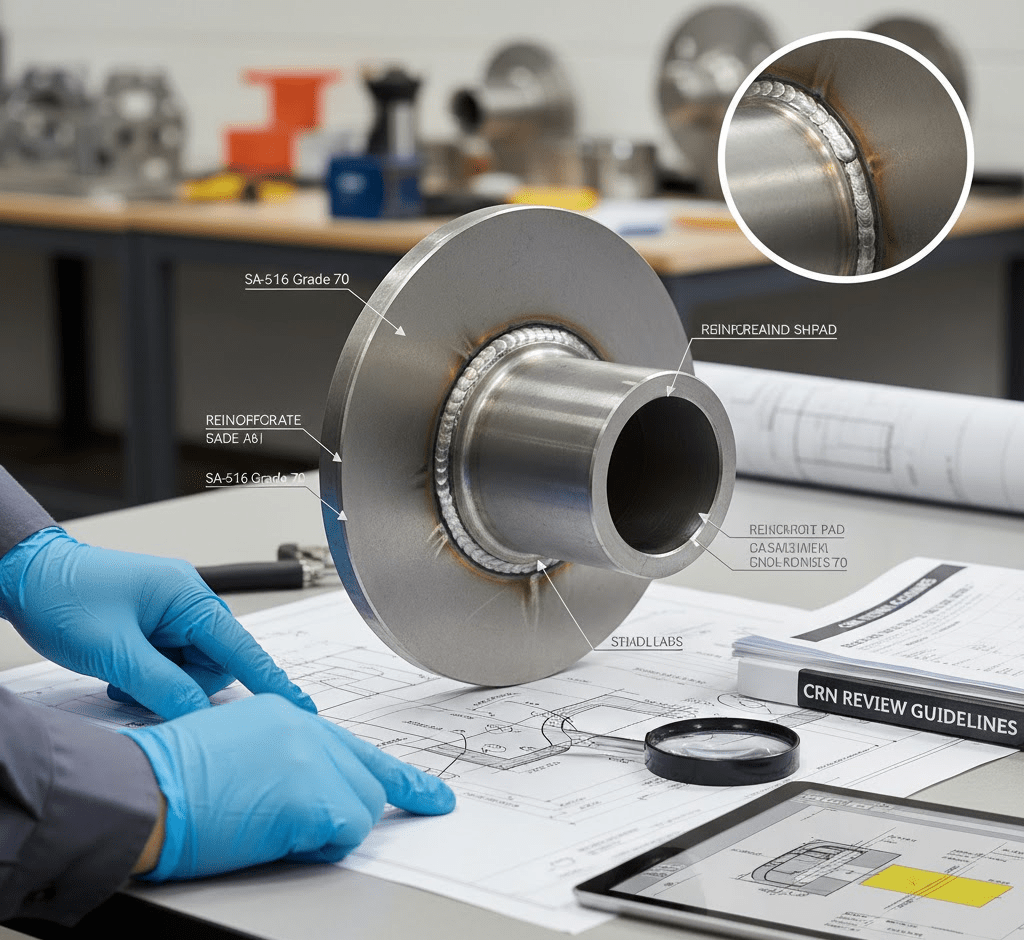
Pressure Vessel Nozzle Reinforcement: What CRN Reviewers Look For Home / Learning Nozzles may seem like minor components in the world of pressure vessel design, but they play a critical role in structural integrity and safe operation. When submitting designs for CRN (Canadian Registration Number) approval, reviewers pay particular attention to nozzle reinforcement — one of the most common areas that can lead to review comments or delays. Why Nozzle Reinforcement Matters? Nozzles are openings in a pressure vessel that allow the passage of fluids, gases, or inspection tools. These openings create localized stress concentrations, which can lead to fatigue, cracking, or even failure if not properly reinforced. That’s why CRN reviewers carefully check nozzle reinforcement calculations and details to ensure compliance with ASME Section VIII, Division 1 or 2, and to confirm that the vessel maintains adequate strength under design conditions. Key Areas CRN Reviewers Evaluate Adequacy of Reinforcement Area Reviewers verify that the nozzle reinforcement area — from weld buildup, reinforcing pads, or excess shell thickness — is sufficient to compensate for the material removed from the vessel wall. The reinforcement must satisfy the minimum requirements of ASME Section VIII. Compliance with Code Requirements All nozzle reinforcement calculations must align with applicable ASME code rules. Reviewers expect to see clear documentation that shows: – Correct use of material properties – Proper design pressures and allowable stresses – Accurate application of code equations and joint efficiencies Proper Detailing in Drawings Beyond calculations, CRN reviewers also look for well-detailed fabrication drawings. These should clearly show nozzle size, orientation, weld configuration, and reinforcement dimensions. Ambiguous or incomplete drawings often cause delays or resubmission requests. How MECS Engineering Supports the CRN Approval Process? At MECS Engineering, our team of Professional Engineering Services brings extensive experience in pressure vessel design and CRN registration. We: Perform detailed code-based reinforcement calculations Prepare complete, regulator-ready drawing packages Verify that all reinforcement requirements are met prior to submission. This proactive approach helps eliminate back-and-forth with provincial reviewers and reduces approval timelines. Experience You Can Trust With years of experience in ASME design and CRN submissions, MECS Engineering has earned a reputation for accuracy, compliance, and technical excellence. We help clients across industries achieve registration success — ensuring that every pressure vessel design meets safety standards without compromising efficiency or reliability.
ASME Section VIII Division 1 vs Division 2: Key Differences for Pressure Vessel Design
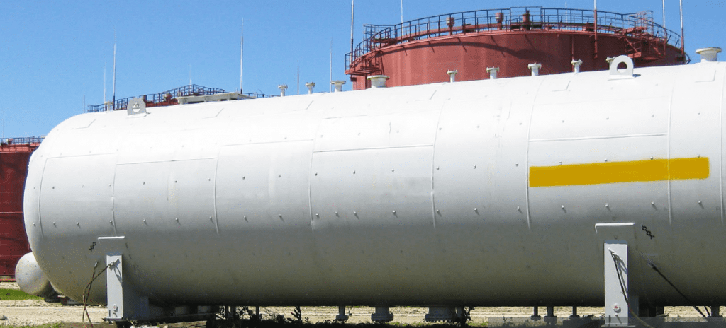
ASME Section VIII Division 1 vs Division 2: Key Differences for Pressure Vessel Design Home / Learning Designing pressure vessels is a critical aspect of industrial engineering. It requires a deep understanding of safety, efficiency, and compliance standards. The ASME Boiler and Pressure Vessel Code (BPVC) Section VIII governs the design and construction of pressure vessels, with Division 1 and Division 2. These are two most widely used standards. At MECS Engineering, our team of Professional Engineering Consultants helps industries navigate these complex codes to ensure safe and cost-effective pressure vessel design. Let’s break down the key differences between Division 1 and Division 2 to help you choose the right approach for your project. 1. Design Philosophy: Simplicity vs Efficiency Division 1 follows a design-by-rule approach. It uses conservative, standardized formulas and guidelines that are relatively straightforward and easy to apply. This division is ideal for most general-purpose vessels. Division 2, on the other hand, employs a design-by-analysis method, allowing for more efficient material use and thinner walls through detailed stress analysis. It’s commonly used for vessels operating at higher pressures or requiring compact designs. 2. Stress Allowances and Safety Factors One of the most significant differences lies in stress limits and safety factors. Division 1 uses a higher safety factor (typically 3.5), making it more conservative but often resulting in heavier, bulkier vessels. Division 2 allows for a lower safety factor (around 3.0) due to its rigorous analysis methods, which can reduce material costs and overall weight. For companies seeking optimization, Division 2 often delivers better long-term value. 3. Fabrication and Inspection Requirements Division 1 offers more flexibility in fabrication methods and typically involves standard inspections and non-destructive testing (NDT). Division 2 requires stricter quality control, more comprehensive documentation, and advanced NDT techniques due to its more complex designs. This makes Division 2 better suited for critical applications in industries like oil & gas, chemicals, and power generation. 4. Application and Cost Considerations While Division 1 is ideal for simple applications with moderate pressure requirements, Division 2 is preferred for high-pressure systems or when material and space savings are crucial. However, the engineering and analysis involved in Division 2 may result in higher upfront costs. At MECS Engineering, our industrial engineering services include evaluating your project’s needs and guiding you toward the most appropriate design code. CONCLUSION Choosing between ASME Division 1 and Division 2 depends on your project’s complexity, budget, and performance requirements. Our experienced Professional Engineering Consultants at MECS Engineering can help you make informed decisions, ensuring both compliance and efficiency.
Thermal Expansion in Piping Systems: Design Mistakes to Avoid
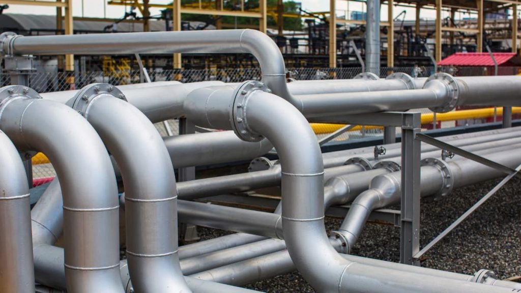
Thermal Expansion in Piping Systems: Design Mistakes to Avoid Home / Learning Thermal expansion is a critical factor in the design and performance of any piping system. Pipelines carry high-temperature fluids, naturally expand and contract. If the expansion and contraction of the pipes (caused by changes in temperature) are not considered during the design of the system, it can cause major problems— – Cracks in the pipes – Leaks at the joints (connections) – Or even the entire piping system failing to work properly. At MECS Engineering, our team of Professional Engineering Consultants helps industries prevent these issues through expert planning and Piping Stress Analysis. In today’s blog, we’ll see the most common design mistakes and their solutions. Mistake 1: Ignoring Thermal Movement in the Design Phase One of the biggest errors in piping system design is failing to allow for thermal expansion. Pipes need space to expand and move. If the design doesn’t allow pipes to safely handle temperature changes, the pressure inside them will grow and cause damage later on. Solution: Use detailed Piping Stress Analysis early in the design phase. Calculate expected expansion and plan accordingly. Mistake 2: Incorrect Placement of Expansion Joints Expansion joints are special parts added to a piping system to handle movement caused by temperature changes (like expansion or contraction). Poor positioning or misalignment may cause stress. And, shift to the other parts of the system. Solution: Engage Professional Engineering Consultants to accurately plan expansion joint placement based on pipe layout, temperature range, and support structures. Mistake 3: Using Rigid Supports for Expanding Pipes Rigid anchors and supports can restrict pipe movement. When thermal expansion is forced against these hard stops, it results in stress points that lead to cracks or leaks. Solution: Use a combination of smart supports that let the pipes move a little when needed. Keep everything strong and in-place. Mistake 4: Overlook Operational Changes Some engineers design based only on the initial operating conditions. They do not consider future temperature changes or equipment upgrades. Solution: Choose an experienced provider of Industrial Engineering Services like MECS Engineering to build flexibility into your system for future-proof performance. CONCLUSION Thermal Expansion is unavoidable. But we can plan for it so that it doesn’t cause any damage. By investing in expert Piping Stress Analysis and working with qualified Professional Engineering Consultants, you can reduce costly repairs. You can also ensure system longevity. At MECS Engineering, we offer advanced Industrial Engineering Services tailored to complex piping systems across industries. Visit us today for smart & stress-free solutions.
Cutting-Edge Industrial Engineering Services for Modern Enterprises: MECS Engineering Inc.

Cutting-Edge Industrial Engineering Services for Modern Enterprises: MECS Engineering Inc. Home / Learning Ever wondered how massive industrial plants keep running smoothly without constant breakdowns? Or how chemical refineries and power stations handle extreme pressures safely every single day? The answer often comes down to industrial engineering services—the quiet, behind-the-scenes backbone of operational excellence. At MECS Engineering Inc., we don’t just design systems; we create solutions that help enterprises work smarter, safer, and more efficiently. Whether you’re overseeing a plant, manufacturing critical components, or coordinating a complex project, industrial engineering is the key to keeping everything running like clockwork. What Industrial Engineering Really Means Industrial engineering isn’t just about crunching numbers or drawing schematics. It’s about making systems work better—reducing waste, preventing failures, and ensuring every process adds value. Imagine a production line where machines frequently stop because a pipeline bursts unexpectedly. That downtime isn’t just frustrating—it’s expensive. Industrial engineers analyze the entire operation, from mechanical loads to workflow efficiency, and design solutions that prevent problems before they occur. That’s what we do at MECS: we combine technical knowledge with real-world experience to ensure your operations are reliable, cost-effective, and compliant with regulations. Why MECS Engineering Inc. Stands Out? Headquartered in Toronto, MECS Engineering Inc. has been helping North American enterprises streamline operations for years. But what truly sets us apart is our hands-on approach. We don’t just deliver reports—we partner with our clients to solve their unique challenges. Our engineers have seen it all: aging piping systems, high-pressure vessels, chemical reactors under stress, and complex process skids. Each project comes with its own quirks, and we thrive on tackling them with innovative, tailored solutions. Key Services Offered by MECS Piping Stress Analysis & Flexibility Studies Pipes are like the veins of a plant—they carry essential fluids, chemicals, or gases. If a pipe fails due to thermal expansion, pressure, or mechanical stress, the results can be catastrophic. MECS uses advanced software to simulate real-world conditions and pinpoint vulnerabilities. We don’t just provide numbers; we provide actionable recommendations that prevent breakdowns and extend the lifespan of your infrastructure. Pro tip from our engineers: A small design tweak early in the planning phase can save hundreds of thousands in maintenance costs down the line. Finite Element Analysis (FEA) Think of FEA as giving your equipment a “stress test” without risking real-world failure. It simulates how structures behave under different forces, helping engineers spot weak points before they become problems. One of our recent projects involved a high-pressure vessel for the chemical industry. Through FEA, we identified a minor design flaw that, if left unchecked, could have led to costly downtime. Fixing it in the design stage saved the client both time and money. Third-Party Verification & Certification Navigating regulations can feel like walking through a maze. MECS provides independent verification, including professional engineering (P.Eng. or P.E.) stamping, so your projects meet legal and safety standards. Clients often tell us, “It’s such a relief to have someone we trust reviewing these complex designs.” That’s because compliance isn’t just paperwork—it’s a safeguard against real risks. Canadian Registration Number (CRN) Support Manufacturing pressure-related components in Canada? CRN approval is mandatory. MECS helps clients with documentation, submissions, and communications with provincial authorities. This support keeps projects moving smoothly and ensures compliance without headaches—a small step that makes a huge difference in large-scale operations. Solutions Tailored to Your Industry Every industry has its own challenges, and MECS doesn’t offer cookie-cutter solutions. Power Sector: Designing systems that endure seismic shocks, thermal expansion, and extreme pressures. Oil & Gas: High-risk environments demand precise calculations and fail-safe designs. Chemical & Petrochemical: Reactors, storage tanks, and pipelines analyzed and optimized for safety and efficiency. Pulp & Paper: Combat aging infrastructure, corrosion, and flow inefficiencies. Process Industries (Food, Pharma): Optimize flow, hygiene, and energy efficiency without compromising safety. By customizing our services, we make sure every client gets solutions that actually fit their operations—not just standard templates. Real-World Examples One oil & gas client faced frequent pipeline failures due to thermal expansion. We performed a detailed piping stress analysis, recommended design adjustments, and monitored the implementation. Result? Downtime reduced by 40% and maintenance costs slashed. Another client, a chemical plant, needed a high-pressure vessel analyzed for compliance. Using FEA and third-party verification, we identified minor stress points and corrected them before production. This avoided delays and ensured safe, uninterrupted operation. These examples illustrate a simple truth: industrial engineering saves time, money, and lives. Why Choose MECS Engineering Inc.? Deep Industry Knowledge: Our engineers have decades of combined experience across multiple sectors. Certified Professionals: P.Eng. and P.E. certifications mean projects meet stringent standards. Practical Solutions: We don’t just analyze; we provide recommendations you can implement. Proven Track Record: Successful collaborations with EPC firms, plant owners, and OEMs across North America. Forward-Thinking Innovation: We leverage advanced software and simulation techniques to stay ahead of industry trends. Conclusion Industrial operations today are more complex than ever. From compliance requirements to efficiency targets, enterprises need solutions that actually work in real life, not just in theory.
Top Challenges in Piping Engineering and How FEA Solves Them
![Professional Engineering Consultants, engineering consulting firms, engineering services, engineering project management, engineering consultancy, engineering consulting, civil engineering consulting, civil engineering services, structural engineering consulting, structural engineering firms, industrial engineering consulting, industrial engineering solutions, environmental engineering consulting, mechanical engineering firms, aerospace engineering consulting, geotechnical engineering services, best structural engineering firm in [city], affordable civil engineering consultants for small projects](https://mecsengineering.com/wp-content/uploads/2025/08/Untitled-design-8-1024x683.jpg)
Top Challenges in Piping Engineering and How FEA Solves Them Home / Learning One of the most important fields in contemporary industrial design, piping engineering ensures that pipelines are safe to carry fluids under any conditions. Despite multiple challenges facing the industry like design complexity, safety issues, and international code compliance, Finite Element Analysis (FEA) steps into the scene as an ace. For any piping engineering company, an integration of FEA with Stress Analysis, Third-Party Verification, and P.Eng./P.E. Certification ensures reliability and compliance at each step. Understanding the Essence of Piping Engineering Piping engineering is concerned with designing, analyzing, and maintaining pipelines that carry liquids, gases, or slurries in the oil & gas, petrochemical, and power generation industries. Designers and analysts need to keep in mind: High-pressure operations Temperature variation Corrosion and material degradation Seismic and environmental conditions Stringent industry regulations Unless proper analysis and code compliance are done, piping failures can result in catastrophic accidents, financial loss, and legal consequences. Key Challenges in Piping Engineering Complex Stress Analysis Pipes are subjected to various types of stresses, thermal, pressure, and external loads. Conventional techniques seldom manage to quantify the nuances of these complexities. Material Selection & Longevity Selecting an appropriate material that resists elevated temperature, corrosion, and fatigue is perhaps the most challenging task for piping engineers. Adherence to International Standards Compliance with ASME, CSA, and ISO codes usually necessitates Third-Party Verification and P.Eng. Certification to ensure engineering reports are certified. Risk of System Failures Leaks, bursts, and vibration problems create operational and safety hazards when not discovered during the design phase. Documentation & Certification Authorities and customers require stamped engineering reports with P.Eng. Stamping or P.E. Certification to guarantee safety and responsibility. What a Finite Element Analysis (FEA) Overcomes These Obstacles? Advanced Stress Analysis Finite Element Analysis (FEA) breaks down complex piping systems into smaller elements and makes it possible for engineers to conduct precise stress analysis on load conditions. This enhances forecasting and minimizes the occurrence of failures. Optimized Material Utilization Through temperature, vibration, and corrosion simulation effects, FEA makes it easy to select cost-effective yet long-lasting materials, prolonging the life of piping systems. Code Compliance & Third-Party Verification FEA reports, when accompanied by Third Party Verification, are in line with industry codes and regulations. A reputable piping engineering firm assures that designs are certified using P.Eng. Certification or P.E. Certification for operational approval. Failure Prevention By simulating extreme conditions (earthquakes, pressure surge, high temperature), FEA identifies weak spots and offers solutions prior to physical application. Certified Engineering Reports Customers are issued professionally stamped reports i.e. P.Eng. Stamping and P.E. Certification, guaranteeing the design is safe and approved for use. Benefits of Integrating FEA with Piping Engineering Improved Safety: Lower risk of leaks, bursts, or catastrophic failures. Cost Economy: Optimized material selection and less downtime. Faster Approvals: Seamless compliance with regulatory codes. Global Credibility: Stamped reports with P.Eng. Certification and P.E. Certification. Trust & Transparency: Independent Third-Party Verification increases confidence with stakeholders. Why Select a Professional Piping Engineering Firm? Utilizing an experienced piping engineering firm guarantees each project is supported by experience in Finite Element Analysis, Stress Analysis, and Third-Party Verification. Furthermore, qualified engineers add P.Eng. Stamping and P.E. Certification, which are required for regulatory and client acceptance. Conclusion Piping engineering is complex, but with Finite Element Analysis (FEA), certified stress analysis, and Third-party verification, companies can eliminate risks and ensure compliance from the start. Partnering with a qualified engineering firm provides the technical rigor, certification, and credibility needed to deliver secure, cost-effective, and globally accepted piping systems.
Top 7 Mistakes to Avoid in Civil and Structure Design Projects

Top 7 Mistakes to Avoid in Civil and Structure Design Projects </h1 > Home / Learning Avoiding critical errors in civil and structure design projects is essential for ensuring safe, efficient, and cost-effective construction. From ignoring site conditions to miscommunication between teams, these mistakes can lead to costly delays and structural failures. In this blog, we will explore the top 7 mistakes to avoid in civil and structure design projects to help engineers, architects, and project managers achieve successful outcomes. 1. Inadequate Site Analysis and Soil Investigation A proper understanding of the site’s geology is the foundation of civil design. Ignoring soil type, bearing capacity, and water table data Overlooking environmental and topographical constraints Relying solely on outdated survey reports Tip: Always conduct geotechnical investigations before beginning the structural design phase. 2. Poor Coordination Between Civil and Structural Teams One of the biggest design risks is poor communication between stakeholders. Lack of integration between architectural, MEP, and structural teams Design conflicts that arise due to missing coordination Delayed revisions increasing project timelines Tip: Adopt BIM tools and regular design reviews to maintain synergy. 3. Underestimating Load Calculations Accurate load calculations are vital to prevent structural failures. Incorrect estimation of dead and live loads Ignoring seismic and wind load effects Inadequate allowance for future expansions Tip: Follow local and international codes like IS 456 or ACI 318 for standard load considerations. 4. Non-Compliance with Local Building Codes Legal issues and penalties can arise from code violations. Designing without considering municipal regulations Not updating plans with the latest code revisions Using obsolete design software that misses compliance checks Tip: Always cross-check designs with applicable civil and structure design regulations. 5. Overlooking Constructability and Site Constraints Practical challenges at the construction site are often ignored during design. Designs that cannot be practically executed onsite Ignoring crane, equipment, or workforce limitations Complex structural elements that delay execution Tip: Involve construction teams during the design phase for better feasibility. 6. Ignoring Sustainability and Material Optimization Overdesigning structures increases costs and environmental impact. Using unnecessarily large cross-sections or materials Not exploring high-performance or eco-friendly materials Excessive concrete usage increasing carbon footprint Tip: Optimize structures with value engineering and sustainable material selection. 7. Lack of Peer Review and Design Validation Skipping quality checks can result in major engineering errors. Designs not peer-reviewed by qualified professionals Absence of stress analysis or FEA where applicable No simulation of load conditions or serviceability Tip: Schedule independent design audits and simulations for large or critical structures. Key Takeaways: What to Remember Always start with a detailed site and soil investigation. Encourage interdisciplinary coordination for integrated design. Prioritize accurate load analysis using verified standards. Comply with building codes to avoid legal setbacks. Consider site constraints and construction feasibility early. Focus on sustainability and resource efficiency. Conduct peer reviews and simulations to validate designs. Avoid Mistakes, Build with Confidence – Partner with MECS Engineering At MECS Engineering, we specialize in civil and structure design solutions tailored to your project needs. Our team ensures full compliance, precision, and performance — from initial surveys to final design validation. Contact us today to schedule a consultation or learn more about how we can help your next project succeed without costly design errors.
How to Perform Stress Analysis in Pressure Vessel Design

How to Perform Stress Analysis in Pressure Vessel DesignLearning Home / Learning In the world of mechanical and process engineering, pressure vessels are essential components used to store and transport pressurized gases and liquids. However, these vessels are constantly subjected to internal pressure, temperature changes, external forces, and more. This is where stress analysis in pressure vessel design becomes crucial—it ensures safety, compliance, and long-term reliability. Why Stress Analysis Is Essential? Pressure vessels operate under harsh and demanding conditions. Without proper stress analysis: Catastrophic failures can occur. Equipment lifespan is reduced. Safety codes and certifications may not be met. Downtime and liability risks increase. That’s why industries such as oil & gas, petrochemical, food processing, and pharmaceuticals rely heavily on accurate stress evaluation and code compliance during the design phase. Key Types of Stress in Pressure Vessels Understanding different stress types helps engineers design vessels that perform reliably. Here are the primary categories: Hoop Stress (Circumferential Stress) Acts tangentially around the vessel’s circumference. Most critical in cylindrical shells. Formula: σₕ = (P × r) / t Longitudinal Stress Acts along the length of the vessel. Generally half of the hoop stress. Formula: σₗ = (P × r) / (2t) Radial Stress Occurs across the wall thickness of the vessel. Minor compared to hoop and longitudinal stress but important in thick-walled vessels. Thermal Stress Caused by temperature differences across the vessel. Can lead to fatigue if not considered in design. Localized or Discontinuity Stress Present near nozzles, welds, supports, and openings. Requires detailed modeling for accurate analysis. Three Main Methods of Stress Analysis 1. Analytical Calculations Based on classical mechanics. Suitable for simple geometries (cylindrical/spherical). Uses thin-wall or thick-wall assumptions. Quick but limited in scope. 2. Code-Based Calculations (ASME, PED, IS Codes) Provide formulas and design criteria based on operating conditions. ASME Section VIII Division 1 & 2 are widely used standards. Ensure safety margins and legal compliance. Used for certification and CRN approvals. 3. Finite Element Analysis (FEA) Advanced computational technique. Ideal for complex geometries and loading conditions. Simulates real-world scenarios including thermal gradients, nozzle loads, and seismic effects. Provides precise insight into stress concentrations and failure points. Step-by-Step: Performing Stress Analysis with FEA Modern design relies heavily on FEA-based stress analysis. Here’s how engineers typically approach it: Step 1: Model the Geometry Start with 3D CAD of the vessel including nozzles, flanges, stiffeners. Simplify wherever possible without compromising accuracy. Step 2: Assign Material Properties Choose materials based on ASME code tables. Include yield strength, thermal conductivity, and Poisson’s ratio. Step 3: Apply Loads & Boundary Conditions Internal/external pressure Dead weight and supports Thermal loads and wind/seismic forces Fixed, pinned, or sliding constraints Step 4: Mesh the Model Create finite elements using a structured or unstructured mesh. Refine mesh near areas of high stress (nozzles, junctions). Step 5: Run Simulation Use solvers (linear static, thermal, or buckling). Observe displacement, von Mises stress, principal stresses. Step 6: Validate and Interpret Results Compare stress values to code-allowable limits. Look for hot spots or discontinuity failures. Evaluate fatigue life if cyclic loading is present. Step 7: Document and Optimize Generate engineering reports with visuals. Recommend reinforcements, thickness changes, or support adjustments. Popular FEA Tools Used for Pressure Vessel Design ANSYS Mechanical SolidWorks Simulation Autodesk Inventor Nastran Abaqus PV Elite (for code-based stress checks) These tools allow integration with design codes and help simulate not just static loading, but also dynamic, thermal, and fatigue conditions. Common Industries Where Stress Analysis is Critical Oil & Gas: Pressure separators, flare stacks, storage tanks Petrochemical Plants: Heat exchangers, reactors Pharmaceutical: Sterile vessels, jacketed tanks Food & Beverage: Steam kettles, CIP vessels Power Plants: Steam drums, boilers, condensers Best Practices for Pressure Vessel Stress Analysis Always use the latest ASME/PED/IS codes. Validate Finite Element Analysis (FEA) models with hand calculations.Use proper mesh convergence studies. Document boundary conditions and assumptions. Include thermal and fatigue analysis in high-temperature applications. Get Expert Help with Your Pressure Vessel Design Performing accurate stress analysis is a technical and regulatory requirement—and it demands experience, certification, and precision. At MECS Engineering, we specialize in: Pressure vessel design and certification FEA simulation for static and thermal stress CRN registration for Canada Code compliance (ASME, CSA, PED) Let our licensed engineers (P.Eng) help you design vessels that are safe, efficient, and fully certified.
Basic and Detailed Engineering: What’s the Difference?

Basic and Detailed Engineering: What’s the Difference? Home / Learning In industrial projects like oil refineries, power plants, or pharmaceutical facilities, success isn’t just about getting the job done. It’s also about being efficient, safe, and keeping costs down. A crucial part of making a project succeed is understanding the difference between basic engineering and detailed engineering design. These two phases are vital at different points in the project, and not recognizing their importance can lead to mistakes, extra work, and delays. In this guide, we’ll break down what each phase involves, how they’re different, and why getting a handle on both is important for a successful project. What Is Basic Engineering? Basic engineering, also known as Front-End Engineering Design (FEED), is the first step of a project where everything starts to take shape. This usually happens after a feasibility study shows that the project makes sense both technically and financially. Key Goals of Basic Engineering: Define what the project will involve Set preliminary specs for equipment and materials Provide rough cost estimates Spot any safety, environmental, and regulatory issues Help with investment choices Basic engineering is important for getting everyone on the same page regarding project goals, risks, and design ideas. It’s all about figuring out what needs to be built and why it matters. Typical Deliverables in Basic Engineering: Process Flow Diagrams (PFDs) Preliminary Piping and Instrumentation diagrams (P&IDs) Overall plant layout Utility needs Initial project timeline and budget Design guidelines for picking equipment In this stage, process engineers, safety engineers, and planners all chip in their ideas, setting the stage for the next step: detailed engineering What Is Detailed Engineering Design? Once the basic design gets the green light, we move on to the detailed engineering design phase. This is where the real work starts, and we turn design ideas into exact specifications for buying materials, building, and getting everything running. Detailed engineering lays out how the project will happen, what materials we’ll use, and how all the systems will work together. Main Goals of Detailed Engineering: Turn basic design into detailed documentation ready for execution Make sure everything meets codes like ASME, API, and CSA Finalize designs for equipment, piping, civil, structure, electrical, and instrumentation Create material take-offs (MTOs) and Bills of Materials (BOMs) Set things up for buying and construction This phase answers the “how,” “where,” and “with what” of the project, involving teams from piping, mechanical, civil, electrical, instrumentation, and control engineering. Read :- Optimizing Industrial Projects Through High-Quality Detailed Engineering Common Deliverables in Detailed Engineering: Final P&IDs and isometric drawings Stress analysis reports for piping 3D plant models using tools like E3D, PDMS, or AutoCAD Plant 3D Structural steel details Cable routing diagrams and electrical load lists Instrument loop diagrams and control system layouts Final project schedule and cost breakdown Basic Engineering vs Detailed Engineering: Key Differences Feature Basic Engineering Detailed Engineering Purpose Define project feasibility and scope Finalize technical specifications for execution Level of Detail High-level and conceptual Fully detailed and construction-ready Output Estimates, layouts, PFDs, preliminary P&IDs 3D models, stress reports, detailed drawings Tools Process simulators, basic CAD CAESAR II, AutoPIPE, E3D, SmartPlant Impact Guides budget and investment Drives procurement, fabrication, and construction Why It’s Important to Know the Difference Not understanding the difference between basic engineering and detailed engineering can cause a bunch of issues like: Confusion between engineering and procurement teams Delays in getting approvals because details are missing More change orders and rework at the site Increased costs from design mistakes Safety risks and issues with codes Having a solid plan for both basic and detailed engineering helps projects run more smoothly, cuts down on surprises, and gives you better control over time and money. How Detailed Engineering Design Helps Projects Succeed Here’s how putting investment into solid detailed engineering design can make a big difference: 1. Better Cost and Material Estimates Having detailed material take-offs and bill of materials means faster and more accurate buying, helping to prevent running short or having too much material. 2. Fewer Construction Delays Clear drawings and 3D models without clashes give construction teams the precise info they need, keeping everything on track. 3. Boosts Safety and Follows Rules Detailed stress tests, load checks, and code compliance ensure the design is safe and meets local requirements, like CRN in Canada. 4. Makes the Most of Equipment and Space By bringing all teams together, detailed engineering helps create efficient layouts that save space and make maintenance easier. 5. Aids in Lifecycle Management Good documentation from the design stage helps with planning maintenance, making changes, and future upgrades. From Basic to Detailed Engineering in an Oil & Gas Project A mid-sized EPC company working on a gas compression station started with a solid basic engineering phase. After getting the client’s approval and the necessary permits, they moved into detailed engineering using SmartPlant and CAESAR II. Here’s what they accomplished: Design approval from regulators in three provinces 15% cost savings from better piping layout No rework during construction Commissioning finished three weeks early. Conclusion Knowing the difference between basic engineering and detailed engineering design isn’t just about having the right skills; it’s about having the right experience for the project. These two steps have distinct roles but they’re essential for making sure everything goes smoothly and stays on budget. If you’re involved in a project—whether you’re a contractor, an engineering company, or the owner—putting time into both basic and detailed engineering is smart. It helps you dodge unexpected issues and deliver your project successfully.
From Concept to Implementation: A Deep Dive into Instrumentation and Controls Design

From Concept to Implementation: A Deep Dive into Instrumentation and Controls Design Home / Learning In today’s world of industrial automation, precision, reliability, and control are essential. Instrumentation and controls design provides the framework to achieve these needs — it is the nervous system of any automated or semi-automated system or process. Be it a power plant, chemical processing plant, or a manufacturing plant, instrumentation and controls systems (I&C) is a vital part to monitor, control, and optimize a process. This article discusses the entire instrumentation and controls design process from the initial conceptual phase to full implementation. We hope to present a view that simplifies an otherwise involved subject down to manageable topics that can be accessed and understood by engineers, project managers, and others in the industry. What is Instrumentation and Control Design? Instrumentation and control design can be characterized as the engineering discipline concerned with creating systems that measure, monitor, and control variables such as temperature, pressure, flow, and level within a process or system. These systems need supply chains, which include a sensor, a transmitter, a controller, and a final control element, such as a valve or relay to provide safe and efficient operations. A well-designed I&C system ensures: Consistent product quality Operational efficiency System reliability Worker safety Regulatory compliance Phase 1: Conceptual Design The journey begins with a clear understanding of the operational needs of a facility. In this phase, engineers and stakeholders define the scope, key process parameters, control objectives, and overall functionality required from the system. Key Steps in Conceptual Design: Requirements Gathering: This involves close consultation with process engineers, operations teams, and safety personnel to identify measurable variables, desired control points, and performance metrics. Feasibility Study: Engineers perform a technical assessment to determine whether current infrastructure can support proposed control solutions, including evaluating power, communication, and space constraints. Preliminary System Architecture: Initial designs include block diagrams of the control hierarchy (field devices, local controllers, remote I/O, HMIs, SCADA integration) and network architecture. Budgeting and Scheduling: Accurate costing of hardware, software, and labor is essential. Scheduling must consider lead times for procurement, manpower availability, and integration milestones. Phase 2: Detailed Engineering Design Once the concept is validated, detailed engineering begins. This is the heart of the instrumentation and controls design process. It involves selecting specific components, creating detailed drawings, and developing the control logic. Main Elements of Detailed Design: P&IDs (Piping and Instrumentation Diagrams): These show interconnections between mechanical systems and control systems, tagging all process sensors, actuators, and control logic references. Instrument Index: A comprehensive list of all instruments, including tag numbers, loop numbers, ranges, and specifications. Loop Diagrams: These document every signal path from the sensor or actuator to the control system and back. They include cable numbers, terminal strips, and power requirements. I/O List: The I/O list maps every analog, digital, and communication signal that must be processed, categorized by source and destination. Control Narratives: These provide a step-by-step description of process control logic, alarm handling, interlocks, and startup/shutdown procedures. PLC/DCS Programming: Engineers develop control algorithms using ladder logic, function block diagrams, or structured text, depending on the controller type. Code is version-controlled and modular for easier troubleshooting. Detailed engineering is collaborative. Electrical, mechanical, and process engineers must work closely to ensure that instrumentation and controls align with all other aspects of the facility. Phase 3: Component Selection and Procurement Component selection is critical to system performance and longevity. The instruments and control hardware must be accurate, durable, and compatible with the process environment (e.g., high temperature, corrosive substances). Factors Influencing Selection: Measurement range and resolution Material compatibility with process media Intrinsic safety and explosion-proof certification Communication capabilities (HART, FOUNDATION Fieldbus, Modbus RTU/TCP, EtherNet/IP) Functional safety ratings (SIL 1/2/3 compliance) MTBF (Mean Time Between Failure) and maintenance requirements Vendor datasheets are analyzed alongside simulation and test results. MECS Engineering uses vendor qualification procedures and long-term performance data to ensure component suitability. Phase 4: Installation and Integration This phase involves the physical installation of instruments, control panels, cabling, and communication systems. Precision is key, as improper installation can compromise system functionality and safety. Key Activities: Instrument Mounting: Engineers ensure process connections are correct (e.g., flange vs threaded) and that mounting orientations match manufacturer specifications to avoid zero shift or signal drift. Cable Routing and Termination: Signal, power, and network cables are segregated to avoid electromagnetic interference (EMI). Grounding and shielding practices follow IEEE/IEC guidelines. Control Panel Assembly: Includes installation of relays, terminal blocks, surge protectors, and power supplies. Panels are labeled per IEC 81346 or ANSI/NEMA standards. Integration with PLC/DCS: Communication between smart instruments and controllers is tested using vendor-specific tools. Engineers validate tag mapping and scaling across the system. Documentation is maintained in real-time using engineering data management software to ensure traceability. Phase 5: Testing and Commissioning Before the system goes live, rigorous testing is performed to ensure everything functions as intended. Types of Testing: Factory Acceptance Testing (FAT): Performed in a controlled environment to verify hardware setup, controller logic, HMI screens, and simulated I/O responses. Site Acceptance Testing (SAT): Conducted on-site to verify integration with actual process equipment. Includes live signal tests, failover testing, and sequence validation. Loop Checks: Technicians use handheld communicators and test equipment to verify that each instrument is connected properly and reads accurately across its entire range. Functionality Testing: Simulates process conditions to ensure that control logic, alarms, and interlocks respond appropriately. Phase 6: Operation and Maintenance Even the best-designed systems require regular maintenance and occasional upgrades. A good I&C design includes features that make maintenance easier, such as diagnostic tools and modular components. Maintenance Best Practices: Scheduled Calibration: Ensures measurement accuracy over time using portable calibrators or in-line calibration systems. Firmware Updates and Patch Management: Keeps controllers and smart devices secure and compatible with evolving software tools. Redundancy Checks: Verifies hot-standby systems and backup power remain functional. Alarm Management: Periodic review of alarm logs ensures nuisance alarms are minimized and critical alarms remain effective. Operational data collected by the I&C system can also
Multidisciplinary Engineering Services and Solutions: Optimizing Efficiency and Safety in Industrial Projects

Multidisciplinary Engineering Services and Solutions: Optimizing Efficiency and Safety in Industrial Projects Home / Learning Introduction In today’s fast-evolving industrial landscape, businesses seek innovative engineering solutions to enhance efficiency, optimize operations, and ensure regulatory compliance. Comprehensive engineering services – spanning mechanical, electrical, instrumentation & controls (I&C), civil, and structural disciplines – play a vital role in supporting industries such as manufacturing, energy, construction, and infrastructure. This article explores key engineering services and their impact on modern industries. Comprehensive Engineering Services and Their Impact 1. Process Optimization and Lean EngineeringEngineering solutions focus on improving workflows, reducing waste, and enhancing productivity through methodologies like Lean Manufacturing and Six Sigma. Key benefits include: Reducing operational costs and cycle times Optimizing resource utilization Improving product consistency and quality Streamlining inventory and supply chain management 2. Multi-Disciplinary Engineering Design and AnalysisEngineering projects require a seamless integration of various disciplines to ensure safety, efficiency, and reliability. Key areas include: Mechanical design and stress analysis Electrical power distribution and automation systems Instrumentation & control system design for process efficiency Civil and structural design for industrial facilities Finite Element Analysis (FEA) for structural integrity 3. Energy Efficiency and SustainabilityWith industries focusing on reducing their environmental footprint, engineering services are critical in implementing: Energy-efficient mechanical and electrical systems Renewable energy integration Smart HVAC and lighting solutions Sustainable materials and construction methods 4. Advanced Piping and Structural EngineeringEnsuring safe and efficient infrastructure requires expert engineering solutions in: Piping stress analysis and fluid flow optimization Structural analysis for equipment skids, piping supports, and buildings Compliance with industry codes and safety regulations 5. Automation and Smart ManufacturingIndustry 4.0 has revolutionized manufacturing and industrial processes through automation. Role of Engineering Services: Robotics and AI-driven control systems IoT-based real-time monitoring and predictive maintenance Smart sensors for performance optimization Human-machine collaboration for enhanced safety 6. Supply Chain and Logistics OptimizationEfficient logistics and material handling strategies help industries improve productivity and reduce costs. Engineering solutions include: Warehouse and distribution center automation Optimized facility layouts for efficient workflows Demand forecasting and inventory management systems 7. Workplace Safety and Regulatory ComplianceEnsuring compliance with industry standards is essential for worker safety and operational continuity. Engineering services cover: Risk assessments and safety audits OSHA and ISO compliance consulting Ergonomic workplace design for employee well-being The Future of Engineering Services As industries evolve engineering solutions will continue to focus on: AI and machine learning for predictive maintenance Advanced automation for process efficiency Sustainable and eco-friendly engineering practices Integration of smart technologies in industrial operations Conclusion Comprehensive engineering services are essential for optimizing industrial operations, ensuring compliance, and achieving long-term success. By integrating multi-disciplinary expertise and cutting-edge technologies, businesses can stay competitive, reduce costs, and enhance productivity in an increasingly complex industrial environment.
