
FEA in Pressure Vessel Design: Moving Beyond Design by Rule
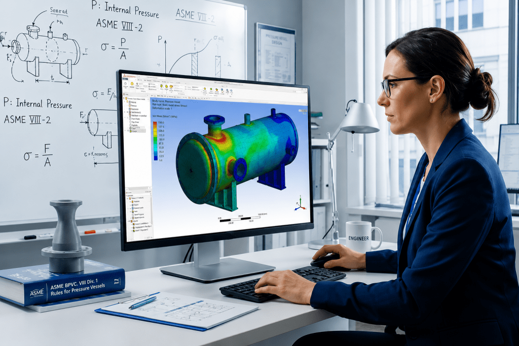
FEA in Pressure Vessel Design: Moving Beyond Design by Rule The global standard method for pressure vessel design has been the “Design-by-Rule” (DBR) methodology governed by popular Boiler and Pressure Vessel Codes like ASME Section VIII, Division 1, AD 2000, PD 5500, EN13445 among others. Design by Rule (DBR) relies on established formulas and safety margins to size components like cylinders, heads, and nozzles. However, these rules only work if you assume the equipment is symmetrical and the loads are simple enough to be conservatively analysed by formula-based methods. The equipment takes physical shape to meet these process demands, the resulting geometry often outgrows the simple mold of established rules in the Code. A vessel’s initial sizing is driven by the process engineer (They dictate exactly what the system needs to function). When a design falls outside the validated scope of standard rules, every major global code provides an “Alternative Design” provision, most famously recognized as ASME Section VIII Division 1’s Paragraph U-2(g) but equally embedded in the core principles of EN 13445, PD 5500, and AD 2000. As, the Code invokes Alternate analysis requirement clause. This clause essentially says if the book doesn’t cover your geometry, you should mathematically prove the design is safe. Alternative Design Provisions (ASME U-2(g), EN 13445, PD 5500, AD 2000) It is a common misconception that triggering these clauses mandates an immediate jump to Finite Element Analysis (FEA). These are Alternative Analysis provisions. They dictate that when the standard rulebook is silent, the engineer is to validate the structural integrity using recognized engineering mechanics. This can be achieved through closed-form analytical calculations (first principles), proof testing, the application of complementary international standards, OR when the geometric complexity outpaces manual mathematics advanced numerical methods like FEA. Let’s Explore what are some potential cases Designers and Engineers can come across which will require them to search beyond DBR methods laid out in the respective Code. In day-to-day static and fixed equipment design, we frequently run into scenarios where standard code rules just aren’t enough. Here are a few of the most common, real-world design issues where FEA becomes an absolute necessity. While the terminology in the examples below leans on ASME Section VIII, Division 1, the underlying physics applies across the board. Because every major “Design by Rule” standard (from EN 13445 to PD 5500) relies on the same basic assumptions of symmetry and uniform loading, they all share the exact same blind spots. Common Real-World Design Scenarios Requiring FEA Local Load Analysis of Geometries Outgrowing WRC LimitsWe use WRC 537 / 107 for analysing static reactions on pressure boundaries, some of the following examples are: Nozzle piping loads on shell and shell to nozzle junction lifting lug and tailing lug attachment to shell. Platform clips and pipe support clips to shell Support legs, Support bracket to shell Nozzle to shell / head junction is overstressed We all rely on WRC 107 / 537 and sometimes WRC 297 to determine local stresses in the shell at structural discontinuities such as legs, support lugs and clip attachments. This bulletin does not address rectangular attachments to shells of double-curvature, and these charts have strict geometric limits. If your nozzle is massive compared to the vessel, or if the shell is extremely thin, or if any rectangular attachment like lug, clips, etc., are welded on double curvature components like heads. WRC methods simply do not provide methods to analyse the concerned geometry. In highly loaded junctions such as a central nozzle supporting an agitator assembly. The standard software with WRC 107 / 537 will provide overstress results and cannot calculate the structural stiffeners. To properly analyze this pressure boundary and guarantee the design is safe, a 3D FEA model is the only practical solution. Non-Uniform Tubesheets Standard TEMA and ASME rules for sizing tubesheets rely on one massive assumption: that the plate is uniformly drilled with holes. For tube layouts which are not uniform where tubesheet is perforated for a small region and large part of it is an untubed area, but real-world heat exchangers often require multi-pass flow, which means there is un-tubed metal. These solid strips act like rigid steel beams. When pressure hits the tubesheet, it doesn’t bend evenly; the un-tubed lanes stay stiff while the drilled areas bow outward. Standard formulas cannot calculate this uneven bending, leading to unexpected shear forces that can rip the tube-to-tubesheet welds apart. As analysts, we model the exact, true geometry of the tubesheet, including every solid un-tubed lane and irregular perimeter gap. This allows the simulation to capture the exact bending behavior and locate the high localized stresses where the flexible tubed region meets the rigid un-tubed metal, ensuring the welds will hold under operating pressure. Large Openings, Extreme Aspect Ratios, and Knuckle Nozzles When you introduce unconventional geometries—like massive openings, obround cutouts, offset/tilted nozzles, or nozzles located right on a head knuckle. Per ASME UG-36(a)(1), if the aspect ratio (the long chord divided by the short chord of the opening) exceeds 2.0, the code warns that additional reinforcement is needed to resist complex bending forces. However, ASME provides no elementary formula for how much reinforcement is needed. Because of this, software will simply flag a permanent warning. This warning will never “disappear” just by artificially thickening the repad in the software, because the error is tied to the physical dimensions of the hole, not the thickness of the steel. The Large Nozzle Limit: If the nozzle is massive, Appendix 1-7(b) takes over. But even those advanced rules have a ceiling. If the ratio of the nozzle radius to the vessel radius exceeds 0.7, the software will complete the Appendix 1-7 analysis but immediately flag that the geometry is still too extreme, requiring additional analysis per U-2(g). Fatigue Life and Cyclic loading Pressure vessels aren’t always static. If a vessel undergoes thousands of pressure or temperature cycles over its lifetime (like a batch reactor continuously filling and draining), the metal can eventually crack from fatigue even if
Stress Analysis: Essential Guide for Piping and Structural Systems
Stress Analysis: Essential Guide for Piping and Structural Systems What Is Stress Analysis? Stress analysis evaluates the internal forces, moments, and deformations that components experience under operational conditions. It identifies potential weak points in a system and predicts how structures or piping networks will respond to loads such as: Internal pressure Thermal expansion and contraction External mechanical forces Vibration and seismic activity By simulating these conditions, engineers can ensure that materials, joints, and supports are properly sized and compliant with relevant codes. Why Stress Analysis Matters in Piping and Structural Design Proper stress analysis benefits both safety and efficiency: Safety Compliance: Correct analysis reduces the risk of mechanical failure, leaks, or structural collapse. Operational Reliability: Ensures systems can handle expected loads, temperature variations, and environmental conditions without premature wear or damage. Key Considerations in Stress Analysis When performing stress analysis, engineers should focus on: Material Properties: Elastic modulus, yield strength, and thermal expansion coefficients. Boundary Conditions: Accurate representation of supports, restraints, and connections. Load Cases: Include all operational, environmental, and accidental conditions. Regulatory Requirements: Consider provincial or state-specific guidelines, especially for pressurized piping systems. Stress analysis software can model complex systems, but professional engineering judgment remains essential to interpret results correctly and implement safe design solutions. How MECS Supports Stress Analysis MECS provides comprehensive stress analysis services for both piping and structural systems. Our team ensures that designs meet safety and regulatory requirements while optimizing performance. Services include: Piping stress analysis for thermal expansion, pressure, and load management Structural analysis of steel and composite frameworks CRN support and P.Eng stamping for compliance Collaboration with project teams for design registration and certification By integrating stress analysis into the early stages of design, we help clients avoid costly rework and ensure operational reliability. Conclusion Stress analysis is essential for safe and efficient piping and structural systems. Whether addressing pressure, thermal loads, or mechanical stresses, professional engineering services ensure compliance, reliability, and optimized performance. For more detailed guidance on stress analysis and engineering support, explore MECS’ full range of services in piping and structural stress analysis.
Stress Analysis Services for Safe and Compliant Industrial Systems

Stress Analysis Services for Safe and Compliant Industrial Systems Stress Analysis serves as a vital engineering discipline, ensuring that structural elements and piping systems can endure external forces, thermal variations, and operational loads without compromise. Throughout the industrial landscapes of the USA and Canada, meticulous Stress Analysis facilitates regulatory adherence, safeguards critical machinery, and minimizes the likelihood of expensive system failures. Within the scope of professional engineering consultancy and services, Stress Analysis is integral to compliance assessments, system upgrades, and plant design. Exhaustive evaluations are essential for both modifications and new builds to confirm that industrial systems operate reliably under actual service conditions. For comprehensive solutions, explore MECS’ specializedhttps://mecsengineering.com/piping-structural-stress-analysis/ What Is Stress Analysis in Industrial Engineering? Stress Analysis evaluates how piping systems and structures respond to loads such as pressure, weight, thermal expansion, wind, and seismic forces. Engineers calculate stresses, displacements, and support reactions to confirm that designs meet allowable limits defined by applicable codes. In practice, this includes: Sustained load evaluation from pressure and weight Thermal expansion and contraction assessment Occasional load checks such as wind or seismic events Equipment nozzle load verification Support and anchor load calculations Professional Stress Analysis ensures that systems comply with standards such as ASME B31.1 and ASME B31.3, while also aligning with provincial and state regulatory requirements. Why Stress Analysis Matters for Compliance and Safety Meeting Code and Regulatory Requirements Industrial projects must comply with recognized engineering codes and, where required, provincial design registration processes. Requirements can vary by province and state, so working with experienced engineers is essential. A properly documented Stress Analysis supports: Design validation before construction Regulatory submissions and reviews P.Eng stamping where required Inspection readiness Applications of Stress Analysis in Piping and Structures Piping Stress Analysis In process and power facilities, piping systems experience significant thermal growth and pressure fluctuations. Piping Stress Analysis ensures flexibility is adequate and support placement is optimized. Structural Stress Analysis Steel structures, pipe racks, and equipment supports must handle combined loads safely. Structural Stress Analysis verifies stability and compliance with applicable building and industrial standards. Choosing the Right Engineering Partner When selecting a provider for Stress Analysis, consider: Experience with North American codes and regulators Capability to provide P.Eng stamped calculations where required Expertise in piping design and structural engineering Clear, practical reporting tailored to regulatory needs An experienced consultancy not only performs calculations but also provides actionable design recommendations that improve constructability and compliance. Conclusion Stress Analysis is more than a technical requirement. It is a fundamental step in ensuring industrial systems operate safely, meet code requirements, and protect long term investments. From piping flexibility reviews to structural load verification, professional engineering expertise makes a measurable difference. If your project requires reliable Stress Analysis backed by practical industry experience, connect with MECS to discuss how our piping and structural stress analysis services can support your next phase of development.
FEA vs Traditional Engineering Calculations: When to Use Each Method
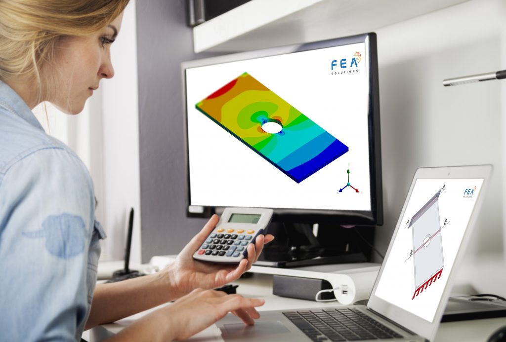
FEA vs Traditional Engineering Calculations: When to Use Each Method Home / Learning Choosing the right analysis method can significantly influence the accuracy, safety, and cost-effectiveness of a project, in modern engineering. Two approaches widely used in modern engineering play essential roles in design and evaluation. These are – FEA (Finite Element Analysis) and traditional engineering calculations. In today’s blog, we’ll understand when to apply each method. And, understand how it helps in reliable results and efficient workflows. Finite Element Analysis Finite Element Analysis is a computer-based technique. It breaks complex structures into smaller & manageable elements. This allows engineers to experience and calculate the real-world conditions, such as stress, heat, vibration, or pressure, with high precision. Companies like MECS Engineering offer Professional Engineering Services. They often rely on FEA for projects requiring detailed insights into how materials or components will behave under various loads. Traditional Engineering Calculations Traditional engineering is an earlier method based on calculations rely on formulas & principles. It is hand-based methods derived from engineering theory. These calculations are often used for simple designs, where the loads and materials behave in predictable ways. They are quick and cost-effective. Also, ideal for great sizing, standard components, and routine design work. When FEA Is the Better Choice FEA is ideal when high accuracy is required or when the structure is too complex for hand calculations. You should choose FEA when: Geometry is irregular or highly detailed, such as pressure vessels with openings or custom piping components. Loads are complex, including thermal, vibrational, or multi-directional stresses. New materials or unique designs are being used, where behavior cannot be easily predicted with formulas. Safety margins must be thoroughly validated. In certain industries, even small errors can cause failures. Finite Element Analysis helps identify weaknesses, optimize design, and reduce the risk of unexpected issues. When Traditional Calculations Are More Suitable Traditional engineering methods are efficient for: Early-stage design and feasibility checks. Simple systems with predictable load paths Code-compliant components, where standard formulas apply Quick assessments without the need for modeling software. These methods provide a strong foundation. They often complement FEA during later phases of the project. Using Both Methods for the Best Results In many cases, the most effective approach is a combination of both. Traditional calculations help narrow down initial design parameters, while FEA validates and refines the final structure. At MECS Engineering, our Professional Engineering Services integrate both approaches to ensure every project meets industry standards, safety requirements, and performance goals.
Finite Element Analysis (FEA) in Pressure Vessel Design: A Practical Guide
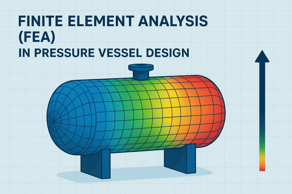
Finite Element Analysis (FEA) in Pressure Vessel Design: A Practical Guide Home / Learning In the field of mechanical and structural engineering, ensuring the safety and efficiency of pressure vessels is critical. These components operate under extreme conditions, where even a small design flaw can lead to catastrophic failure. This is where Finite Element Analysis (FEA) plays a crucial role. As part of Professional Engineering Services, FEA enables engineers to predict and prevent potential issues before manufacturing begins. 1. Understanding Finite Element Analysis (FEA) Finite Element Analysis (FEA) is a simulation-based method used to evaluate how a structure reacts to real-world forces such as pressure, heat, and vibration. By breaking down a complex pressure vessel into small, manageable elements, engineers can analyze stress distribution, deformation, and potential weak points with high precision. This analytical method allows Professional Engineering Services providers like MECS Engineering to deliver designs that meet stringent safety standards and comply with international codes, such as ASME and API. 2. The Role of FEA in Pressure Vessel Design Pressure vessels are exposed to internal and external loads that vary depending on the process they support. Using FEA, engineers can simulate these operating conditions digitally and assess how materials and geometries perform under stress. Key insights gained from FEA include: Stress concentration areas that may lead to fatigue or failure. Optimal thickness and material selection for the vessel wall. The effect of temperature and pressure variations on performance. Verification of design against code requirements. By identifying these factors early, Finite Element Analysis minimizes the need for physical prototypes, saving time and cost while enhancing design reliability. 3. Benefits of Using FEA in Engineering Projects Integrating FEA into Professional Engineering Services provides several advantages: Enhanced Safety: Detect potential weak spots before fabrication. Cost Efficiency: Reduce material waste and manufacturing errors. Improved Performance: Optimize design for durability and efficiency. Regulatory Compliance: Ensure designs meet ASME and industry codes. At MECS Engineering, FEA forms the backbone of every pressure vessel design, ensuring each project is not only efficient but also built to last. 4. Partnering with Experts in FEA and Pressure Vessel Design Choosing a trusted engineering partner is vital. MECS Engineering combines years of expertise with cutting-edge simulation tools to provide reliable, compliant, and cost-effective solutions. Whether you need detailed Finite Element Analysis or complete Professional Engineering Services, MECS Engineering ensures precision, performance, and peace of mind at every stage of your project.
How to Perform Stress Analysis in Pressure Vessel Design

How to Perform Stress Analysis in Pressure Vessel DesignLearning Home / Learning In the world of mechanical and process engineering, pressure vessels are essential components used to store and transport pressurized gases and liquids. However, these vessels are constantly subjected to internal pressure, temperature changes, external forces, and more. This is where stress analysis in pressure vessel design becomes crucial—it ensures safety, compliance, and long-term reliability. Why Stress Analysis Is Essential? Pressure vessels operate under harsh and demanding conditions. Without proper stress analysis: Catastrophic failures can occur. Equipment lifespan is reduced. Safety codes and certifications may not be met. Downtime and liability risks increase. That’s why industries such as oil & gas, petrochemical, food processing, and pharmaceuticals rely heavily on accurate stress evaluation and code compliance during the design phase. Key Types of Stress in Pressure Vessels Understanding different stress types helps engineers design vessels that perform reliably. Here are the primary categories: Hoop Stress (Circumferential Stress) Acts tangentially around the vessel’s circumference. Most critical in cylindrical shells. Formula: σₕ = (P × r) / t Longitudinal Stress Acts along the length of the vessel. Generally half of the hoop stress. Formula: σₗ = (P × r) / (2t) Radial Stress Occurs across the wall thickness of the vessel. Minor compared to hoop and longitudinal stress but important in thick-walled vessels. Thermal Stress Caused by temperature differences across the vessel. Can lead to fatigue if not considered in design. Localized or Discontinuity Stress Present near nozzles, welds, supports, and openings. Requires detailed modeling for accurate analysis. Three Main Methods of Stress Analysis 1. Analytical Calculations Based on classical mechanics. Suitable for simple geometries (cylindrical/spherical). Uses thin-wall or thick-wall assumptions. Quick but limited in scope. 2. Code-Based Calculations (ASME, PED, IS Codes) Provide formulas and design criteria based on operating conditions. ASME Section VIII Division 1 & 2 are widely used standards. Ensure safety margins and legal compliance. Used for certification and CRN approvals. 3. Finite Element Analysis (FEA) Advanced computational technique. Ideal for complex geometries and loading conditions. Simulates real-world scenarios including thermal gradients, nozzle loads, and seismic effects. Provides precise insight into stress concentrations and failure points. Step-by-Step: Performing Stress Analysis with FEA Modern design relies heavily on FEA-based stress analysis. Here’s how engineers typically approach it: Step 1: Model the Geometry Start with 3D CAD of the vessel including nozzles, flanges, stiffeners. Simplify wherever possible without compromising accuracy. Step 2: Assign Material Properties Choose materials based on ASME code tables. Include yield strength, thermal conductivity, and Poisson’s ratio. Step 3: Apply Loads & Boundary Conditions Internal/external pressure Dead weight and supports Thermal loads and wind/seismic forces Fixed, pinned, or sliding constraints Step 4: Mesh the Model Create finite elements using a structured or unstructured mesh. Refine mesh near areas of high stress (nozzles, junctions). Step 5: Run Simulation Use solvers (linear static, thermal, or buckling). Observe displacement, von Mises stress, principal stresses. Step 6: Validate and Interpret Results Compare stress values to code-allowable limits. Look for hot spots or discontinuity failures. Evaluate fatigue life if cyclic loading is present. Step 7: Document and Optimize Generate engineering reports with visuals. Recommend reinforcements, thickness changes, or support adjustments. Popular FEA Tools Used for Pressure Vessel Design ANSYS Mechanical SolidWorks Simulation Autodesk Inventor Nastran Abaqus PV Elite (for code-based stress checks) These tools allow integration with design codes and help simulate not just static loading, but also dynamic, thermal, and fatigue conditions. Common Industries Where Stress Analysis is Critical Oil & Gas: Pressure separators, flare stacks, storage tanks Petrochemical Plants: Heat exchangers, reactors Pharmaceutical: Sterile vessels, jacketed tanks Food & Beverage: Steam kettles, CIP vessels Power Plants: Steam drums, boilers, condensers Best Practices for Pressure Vessel Stress Analysis Always use the latest ASME/PED/IS codes. Validate Finite Element Analysis (FEA) models with hand calculations.Use proper mesh convergence studies. Document boundary conditions and assumptions. Include thermal and fatigue analysis in high-temperature applications. Get Expert Help with Your Pressure Vessel Design Performing accurate stress analysis is a technical and regulatory requirement—and it demands experience, certification, and precision. At MECS Engineering, we specialize in: Pressure vessel design and certification FEA simulation for static and thermal stress CRN registration for Canada Code compliance (ASME, CSA, PED) Let our licensed engineers (P.Eng) help you design vessels that are safe, efficient, and fully certified.
FEA vs Traditional Calculation: Which One Should You Choose?

FEA vs Traditional Calculation: Which One Should You Choose? Home / Learning In today’s engineering world, getting accurate designs is super important. One topic that sparks a lot of debates among engineers and project managers is whether to go with Finite Element Analysis (FEA) or stick to traditional calculation methods. At MECS Engineering, we focus on providing FEA services that cater to complex industry needs. So, how do you figure out which method is right for your project? Let’s break it down. What is Finite Element Analysis (FEA)? FEA is a computer simulation method that helps predict how a product or structure will react to real-world forces like heat, vibration, fluid flow, and stress. It breaks down complicated shapes into smaller parts, or elements, so engineers can run thorough simulations. Benefits of FEA High accuracy in analyzing stress and strain. Works well with complex shapes and load conditions. Can lower costs for physical prototypes. Provides visual results that are easy to understand. At MECS Engineering, we use FEA to check the reliability of pressure vessels, piping systems, and structural components. What are Traditional Engineering Calculations? Traditional calculations involve manual or spreadsheet methods using formulas from engineering standards like ASME, API, or ISO codes. They’re often used for simpler designs or when code compliance is straightforward. Advantages of Traditional Calculations Quick for basic shapes and load scenarios. Grounded in established standards. Great for initial design and feasibility checks. That said, traditional methods might not provide the detail and accuracy needed for more complicated systems. When to Use FEA Designing pressure vessels with varying wall thickness. Analyzing high-stress spots in pipes and mechanical parts. Evaluating failure points under changing loads. Dealing with odd shapes or boundary conditions. If your project needs precision and reliability, FEA is usually the better option. That’s where MECS Engineering comes in with solid, certified FEA solutions. When to Stick with Traditional Calculations Simple, symmetric designs. Early sizing and layout work. Structures that clearly follow code guidelines. MECS Engineering also supports traditional methods when needed, ensuring you get the best solution every time. Conclusion: Choose What Works for Your Project Both FEA and traditional calculations have their uses. For high-risk or complex designs, FEA provides the insight you need. For simpler tasks, traditional methods can be effective and trustworthy. At MECS Engineering, we combine traditional engineering principles with advanced FEA to optimize your design for safety, compliance, and performance. Reach out to our expert team to see how we can help you.
