
Piping in Canada and Why a CRN Number Matters
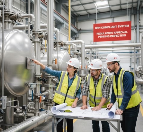
Piping in Canada and Why a CRN Number Matters Across Canada, pressure piping and other pressure equipment must meet provincial safety requirements. One of the most important compliance items is the Canadian Registration Number (CRN), which confirms that a pressure equipment design has been accepted by a Canadian jurisdiction’s regulator. For companies executing piping projects in Canada, understanding when CRN registration applies and planning for it early can prevent schedule delays and costly rework. What is a CRN Number? A CRN is a unique identifier issued by a Canadian jurisdiction (province or territory) to indicate that a pressure equipment design has been reviewed and registered in accordance with applicable Canadian requirements. Depending on the scope, CRNs may apply to items such as pressure vessels, fittings, valves, and certain piping systems or assemblies. Because pressure equipment regulation is handled at the provincial/territorial level, registration is jurisdiction-specific. A design registered in one province may require registration in other provinces where the equipment will be manufactured, installed, or operated. Why CRN Planning Matters for Piping Projects in Canada For piping projects, CRN-related requirements can affect: procurement (purchasing “CRN-ready” components versus custom items needing registration) fabrication and inspection planning installation schedule and turnover documentation If a CRN is required and the design is not registered in time, projects can be delayed at the fabrication, installation, or commissioning stage. Early clarity on the registration scope (what needs a CRN and in which jurisdictions) is often the simplest way to protect schedule and budget. Jurisdictional Expectations and CRN-Related Piping Stress Review Regulator expectations can differ across Canada. For example, Alberta (ABSA) and Ontario (TSSA) may have different submission conventions, review focus areas, and documentation preferences. For pressure piping, regulators and authorized inspection agencies typically expect engineering packages that clearly demonstrate code compliance (commonly ASME B31.3/B31.1 or other applicable B31 codes, depending on service). Where applicable, a piping stress analysis is often part of demonstrating: adequate flexibility and thermal expansion control sustained and occasional load compliance support and restraint philosophy equipment nozzle load management (where required by the equipment vendor or project specifications) A well-prepared CRN submission avoids gaps such as unclear design conditions, incomplete material traceability, inconsistent code references, or missing stress justification where it is needed. How MECS Engineering Supports CRN Compliance MECS Engineering supports clients across Canada by aligning piping design documentation with regulator expectations and project realities. Our team routinely coordinates with jurisdictions such as ABSA and TSSA and helps clients reduce back-and-forth during review. Typical support includes: scope definition for CRN planning (what must be registered, and where) design review and compliance checks for pressure piping and related pressure equipment piping stress review/analysis support where required for compliance or risk reduction preparation and completion of submission packages and responses to regulator comments Why MECS Engineering MECS Engineering provides end-to-end support for pressure piping and pressure equipment compliance in Canada, with a practical focus on “getting it accepted” while protecting the project schedule. By addressing jurisdiction-specific requirements early, we help clients avoid common causes of CRN delays such as incomplete design conditions, documentation gaps, or inconsistent engineering basis. Summary CRN registration is more than paperwork—it is a critical compliance step that protects safety, reduces project risk, and supports smooth fabrication, installation, and inspection. If you are executing a piping project in Canada and need clarity on CRN scope or support with submissions, MECS EngineeringMECS Engineering can help you move from design to approval with fewer surprises.
Piping Engineering: Streamlining Industrial Systems with Expertise

Piping Engineering: Streamlining Industrial Systems with Expertise In industrial facilities, piping is the circulatory system that keeps operations running. Whether the service is steam, condensate, hydrogen, natural gas, chemicals, glycol, or utilities, piping must be engineered to operate safely under pressure and temperature, integrate properly with connected equipment, and meet code and provincial/state requirements. Piping engineering focuses on practical, buildable design that supports safe operation, maintainability, and long-term reliability. It includes routing and layout, material selection, flexibility and support philosophy, interface management with equipment and structures, and engineering checks that confirm the system will perform as intended throughout its life. Why piping engineering services are essential Poorly engineered piping can create consequences that are expensive and disruptive: unexpected loads on equipment nozzles, vibration and fatigue failures, thermal expansion problems, leaks, rework during installation, and delays during regulator or third-party reviews. Strong piping engineering reduces these risks early, when changes are least costly. Key components of piping engineering services Piping design and layoutDeveloping routing that is constructible and maintainable, selecting materials and components, defining insulation and heat tracing interfaces, and coordinating with structural and mechanical constraints. Piping flexibility and stress analysisEvaluating sustained, thermal expansion, and occasional loads to confirm compliance with the governing code and to protect connected equipment. This includes support locations, anchor and guide strategies, nozzle load checks (as applicable), and practical recommendations to reduce field changes. Isometrics and fabrication-ready deliverablesProducing accurate isometrics, bill of materials, weld maps (when required), and installation details that support fabrication and construction execution. Code and regulatory complianceConfirming alignment with applicable standards such as ASME B31.1, ASME B31.3, ASME B31.9, and project specifications, along with local jurisdictional requirements that vary by province and state. Jurisdictional expectations and pressure piping registrationIn Canada, pressure piping requirements are jurisdiction-driven. Expectations can differ between provinces, even when the same ASME piping code is used as the design basis. For example, Alberta and Ontario have established design submission practices through ABSA and TSSA, respectively, and reviewers typically expect a complete, coherent package that connects the engineering intent to code compliance. A pressure piping submission commonly requires items such as: piping line list and design conditions (pressure, temperature, fluid service, corrosion allowance) P&IDs tied to specifications piping material specifications and component standards supports and flexibility philosophy stress analysis (when required by service, size, temperature, layout complexity, or jurisdictional expectations) consistent documentation that aligns design basis, calculations, and drawings CRN-related piping stress review (where CRN fits) CRN registration applies to pressure-retaining components (such as fittings, valves, flanges, and some assemblies) that are registered for use in Canadian jurisdictions. Piping systems themselves are typically handled through pressure piping design registration requirements rather than CRN, but the two often intersect in real projects. MECS frequently supports clients where piping stress analysis and regulator-facing documentation must align with registered components and jurisdictional review expectations. When a project includes CRN-registered components (or requires new CRNs for specific items), the piping design and stress review should be consistent with: the component design limits and ratings the specified materials and corrosion allowances the project design basis and operating scenarios the submission package logic that regulators expect (traceability and consistency across documents) How MECS Engineering supports industrial projects MECS Engineering provides piping engineering services that are grounded in real execution and regulator expectations. Our team supports clients across multiple jurisdictions, including projects involving ABSA and TSSA reviews, where completeness, clarity, and code alignment matter as much as the calculations. MECS support can include: piping stress analysis and flexibility studies for critical systems design review and compliance verification for piping packages constructability input and support optimization to reduce field changes regulator-ready documentation support aligned with project scope and jurisdictional requirements coordination with mechanical, structural, and process disciplines to prevent interface issues Value of professional piping engineering Piping engineering is not only a design activity; it is risk control. A well-engineered piping system improves safety, reduces downtime, supports reliable operation, and prevents expensive construction rework. With MECS Engineering, clients get practical engineering backed by code knowledge and experience working with jurisdictional expectations.
Essential Guide to Piping Stress Analysis and Piping Flexibility
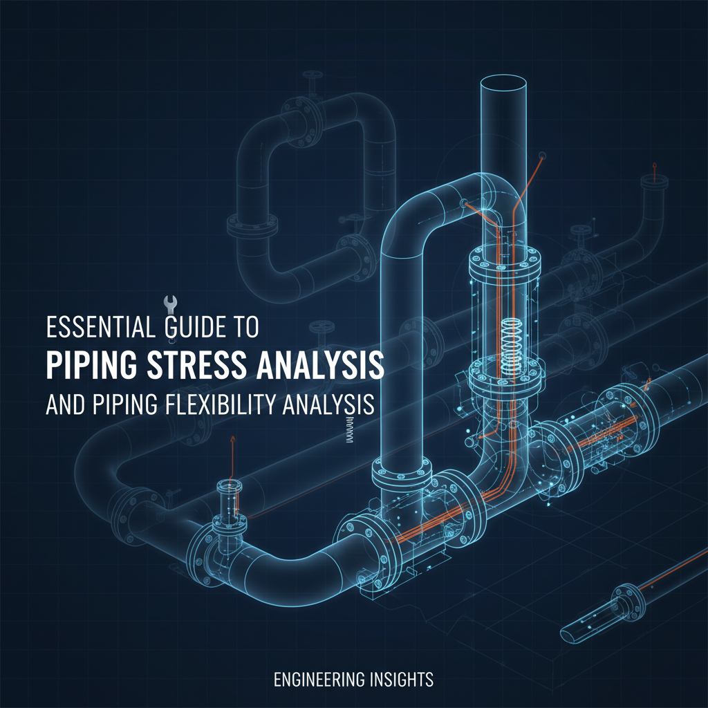
Essential Guide to Piping Stress Analysis and Piping Flexibility Industrial piping systems are subjected to pressure, temperature changes, weight, and external loads throughout their operating life. If these effects are not properly evaluated during design, the result can be excessive stresses, equipment damage, leaks, or premature failure. This is why piping stress analysis, including flexibility evaluation, is a critical part of safe and compliant piping system design. Understanding piping stress analysis Piping stress analysis is an engineering evaluation of how a piping system behaves under various loading conditions. These loads typically include internal pressure, pipe weight, fluid weight, thermal expansion, wind, seismic effects, and occasional loads such as relief valve discharge or slug flow. The objective is not only to check pipe stresses against allowable limits defined by applicable design codes, but also to verify that loads transmitted to connected equipment, supports, and structures remain within acceptable limits. Stress analysis is commonly required for: High-temperature systems Large-diameter or long pipe runs Systems connected to sensitive equipment such as pumps, compressors, turbines, and pressure vessels Why piping stress analysis is critical Failure to perform proper stress analysis can lead to: Excessive nozzle loads on equipment, resulting in misalignment or mechanical failure Cracked welds or flange leaks caused by thermal expansion Support failures or unexpected load transfer to structures From both safety and cost perspectives, identifying these issues during design is far more effective than correcting them after installation. Stress versus flexibility: clarifying the relationship Flexibility is not a separate analysis performed in isolation. It is an integral part of piping stress analysis. Piping flexibility evaluation focuses on whether a piping system can absorb thermal expansion and contraction without generating excessive stress or unacceptable equipment loads. This is achieved through routing, layout geometry, expansion loops, offsets, and appropriate support selection. A piping system may meet allowable stress limits but still be unacceptable if it imposes excessive loads on equipment nozzles or supports. Conversely, a flexible system with poor support design may experience vibration or fatigue issues. A proper stress analysis addresses both aspects together. Thermal expansion and movement Thermal expansion is one of the most significant drivers of piping stress. Even relatively short pipe runs can generate large forces when restrained. Stress analysis evaluates: Expansion stress ranges Anchor and restraint forces Displacements at key locations Effects of operating, startup, shutdown, and upset conditions Accounting for thermal movement early in the design stage helps avoid late-stage layout changes, additional supports, or expansion joints. Supports and restraint design Pipe supports are a critical part of the stress analysis model. Their type, location, and stiffness directly affect system behavior. Common considerations include: Rigid supports versus spring supports Vertical load distribution Line stops, guides, and anchors Cold versus operating loads Allowable loads on structures and foundations Improper support design is one of the most frequent causes of piping stress issues identified during review. Role of software and engineering judgement Specialized software such as CAESAR II is widely used to perform piping stress analysis. These tools allow engineers to model complex systems and evaluate multiple load cases efficiently. However, software alone does not ensure a correct design. Engineering judgement is required to: Define realistic boundary conditions Select appropriate load combinations Evaluate support behaviour Interpret results in line with code intent and project requirements Manual checks and independent verification remain an important part of good engineering practice. Practical best practices Integrate stress analysis early in layout and routing development Coordinate closely with piping designers, structural engineers, and equipment vendors Verify nozzle loads against vendor or code limits Review stress results together with support loads and displacements Revisit the analysis whenever significant design changes occur Frequently asked questions Why is piping stress analysis required by regulators and clients? Because it demonstrates that the piping system meets code requirements and will operate safely without overstressing pipes, equipment, or supports. Is flexibility analysis always required? Flexibility evaluation is required whenever thermal expansion or movement could cause excessive stress or loads. In practice, this applies to most industrial piping systems. When should stress analysis be updated? Whenever there are major routing changes, temperature or pressure changes, support modifications, or equipment changes. Conclusion Piping stress analysis, including flexibility evaluation, is essential for safe, reliable, and compliant piping systems. It reduces failure risk, protects connected equipment, and prevents costly modifications during construction and operation. For projects involving regulatory review or equipment registration interfaces, producing a clear and defensible package is as important as the calculations themselves. MECS Engineering supports clients with both the technical analysis and the documentation quality needed to reduce approval risk and keep projects moving.
The Ultimate Guide to Piping Flexibility and Stress Analysis Techniques
The Ultimate Guide to Piping Flexibility and Stress Analysis Techniques I remember the first time I bumped into the term “piping flexibility analysis.” Honestly, back then, I didn’t quite get it. Who really does at first? But if you’ve ever gotten yourself all tied up in piping systems—whether literally or just in your head—you’re catching my drift. Let’s be real, these setups might as well be a game of Twister, yet they’re crucial for many industrial setups. Nailing flexibility and stress analysis is critical. Yeah, really. It’s no walk in the park, trust me. Why Is Piping Flexibility Important? Ever wonder why some pipes last forever, while others burst outta nowhere? It’s all about flexibility. But here’s the twist—it doesn’t mean they’re flimsy. It’s like a dance between strength and flexibility. You want those pipes to take the pressure, literally, but also give a little with temperature changes. It’s basically yoga for pipes. The Basics You Can’t Skip Look, let’s break it down. Piping flexibility analysis makes sure pipes handle thermal expansion, movements, and avoid stressing out supports for no reason. The goal? Predict how pipes act in different scenarios. And imagine the mess if we hadn’t gotten it figured out. I learned the hard way, a little more effort in analysis saves a ton of trouble down the line—but it’s easy to forget about. Just like that one time, I thought duct-taping a leaky pipe would magically fix it. Spoiler alert: it didn’t. Too Rigid or Too Loose? It’s a delicate act. Too stiff, and the pipes might just crack under pressure. Too wobbly? Well, they’ll be all over the place. You need them to be stable—kind of like teens learning to drive. This means analyzing stress analysis to foresee how pipes hold up under different loads. Diving Deep: The Techniques So you’re not just gonna wing it? Smart move. Now, let’s dive into these techniques. I’ll guide you through some I’ve found both mesmerizing and sometimes frustratingly precise. Precision’s the game here, after all. Understanding Flexibility Factors Real talk: flexibility factors are like the coach for your pipes. They reveal just how much your pipes can take before they tap out. Gone through this balancing act? You factor in bending radius, materials and more (copper bends differently than steel, who knew?). One time, I underestimated those during a project, learned my lesson the expensive way. Nailing these numbers is like finding the perfect pinch of salt in a recipe—get it wrong and it’s disaster city. Stress Are Us: The Analysis Process Onto stress analysis. This is where the magic of engineering comes alive. You become Sherlock Holmes, sleuthing out potential fail points. You nail down stress levels and set those all-important limits to keep things safe and compliant. Fun, right? Establish a baseline: Know where your piping starts. Conduct static analysis: Grasp that starting stress level. Dynamic analysis: Often skipped but so vital, it’s like future-proofing. Dynamic analysis can feel like a labyrinth (and let’s be real, it can get costly), but skipping it is like skipping dessert. You’ll definitely miss something big. Lessons From the Field Real talk—every project ain’t the same, and you gotta roll with it. Here’s what my experience taught me in the piping analysis arena. Lesson One: Expect the Unexpected I remember this one time at a chemical plant where assumptions nearly caused a big crisis. The materials weren’t what the specs had promised. We had to re-analyze everything! It’s like never assuming life in the field will be all smooth sailing. Lesson Two: Software Is Your Friend In today’s world, turning a blind eye to simulation software? You can’t afford that. I’ve used tools like CAESAR II and ROHR2, which ran some serious analysis gigs. These tools can solve stress equations worthy of Einstein, no cap. Still relying on gut feeling? Rethink that. It’s the digital age. Let computers do the muscle work, for real. FAQs On Piping Flexibility Analysis I get asked a ton of questions on this, and it makes sense. So let’s dive into these frequent flyers. What’s the biggest mistake in flexibility analysis?People often lean too much on “rules of thumb.” They’ve got their place, but specialized analysis designed for your setup is king. How often should I carry out a stress analysis?Before any temperature rise or load changes rock the boat. Seriously, these can’t be stressed enough (pun intended). Is software analysis foolproof?From my perspective? Nothing’s perfect. Software rocks, but human insight remains priceless. Together? It’s magic. Can pipe flexibility save money?For sure. Proper analysis negates costly downtimes, plus skirts around safety hazards (and lawsuits, yikes!). How does temperature affect piping flexibility?Like, significantly. Temperature swings cause expansion or shrinking, left unchecked it can crumble everything. It’s like winterizing your home—don’t cut corners. Final Thoughts And that’s a wrap. Gotlar spiritsrudfreeze mastering piping flexibility analysis a saves you from being a cautionary tale. I’m still learning in this growing field. But these rules? They’re your fast track to saving months. Seriously, take it from me.
Why Outsourcing Piping Stress Analysis to Experts Saves Time & Money

Why Outsourcing Piping Stress Analysis to Experts Saves Time & Money </h1 > Home / Learning It is important to make sure all piping systems work safely and smoothly in big industrial projects. Piping stress analysis plays an important role here. However, to complete this task, anyone can take a significant amount of time, costly software, and professional experts. That’s why many companies are outsourcing this work to specialists. Partnering with professionals not only improves accuracy but also delivers major savings in both time and budget. At MECS Engineering, we provide the best solutions to you for outsourcing piping stress analysis. Use of Advanced Expertise and Tools Outsourcing Piping Stress Analysis gives you direct access to experienced engineers who specialise in evaluating pipe flexibility, thermal expansion, vibration, and load conditions. These experts use advanced modelling tools and industry-leading software that many companies may not possess internally. By working with a team like MECS Engineering, that provides Professional Engineering Services, you ensure that your project complies with the latest codes and standards, which reduces risk and prevents costly design errors. On the other hand, handling this in-house without the right expertise may lead to rework, unexpected failures, or delays. Faster Project Delivery Time is one of the biggest advantages of outsourcing. Engineering organisations that offer specialised industrial engineering services have streamlined workflows to process Piping Stress Analysis efficiently. Their teams work on these calculations daily, meaning they can complete tasks quicker and more accurately than a general in-house team. Faster analysis means faster approvals, which ultimately speeds up the entire project timeline. This allows your internal staff to focus on core engineering tasks rather than getting tied down by complex stress calculations. Significant Cost Savings Outsourcing eliminates the need to invest in expensive software licences, training programs, and additional staff. Instead, you pay only for the services you need. This reduces overhead costs while still ensuring that the work is completed by qualified professionals. Moreover, accurate stress analysis helps avoid structural issues, pipe failures, safety hazards, and shutdowns—each of which can be extremely costly. Working with experts ensures that potential problems are identified early, preventing expensive repairs or downtime later on. Improved Safety Professional engineering teams ensure that your piping system meets all relevant industry codes, safety standards, and best practices. Their experience across various industrial environments—refineries, power plants, manufacturing facilities—means they understand real-world challenges and design solutions that enhance overall safety. Reliable compliance also increases the long-term performance of your systems, reducing maintenance issues and supporting smoother operations. CONCLUSION Companies require accuracy, efficiency, and cost savings. So, they do Outsourcing Piping Stress Analysis. It’s a smart choice. Partner with a team like MECS Engineering that offers Professional Engineering Services and comprehensive industrial engineering services. You can streamline your project, reduce risks, and ensure safe and efficient piping systems.
When Do You Need a Piping Stress Analysis? Real-World Scenarios
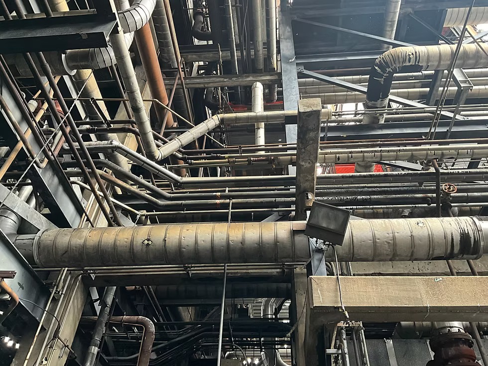
When Do You Need a Piping Stress Analysis? Real-World Scenarios </h1 > Home / Learning In industrial systems, piping networks are more than just connectors between equipment—they’re critical infrastructure that must operate safely and efficiently under various mechanical and thermal conditions. One of the key tools to ensure this integrity is Piping Stress Analysis. At MECS Engineering, our team of Professional Engineering Consultants regularly performs stress analysis to support safe, compliant, and cost-effective designs. But when is this type of analysis necessary? Let’s explore real-world scenarios where Piping Stress Analysis becomes essential. 1. High-Temperature or High-Pressure Systems In industries such as oil and gas, chemical processing, or power generation, piping often carries fluids at extreme temperatures or pressures. These conditions can cause expansion, contraction, and stress concentrations that lead to fatigue or failure. Piping Stress Analysis helps predict how piping systems will behave under such extremes, ensuring proper supports, materials, and expansion loops are used to manage movement safely. 2. Connecting Rotating or Sensitive Equipment When piping is connected to pumps, compressors, turbines, or other sensitive machinery, excessive forces or misalignment can cause equipment failure or downtime. To avoid costly repairs or operational losses, stress analysis ensures that thermal growth or pipe loads do not exceed the allowable limits for connected equipment. 3. Code Compliance and Safety Regulations Australian and international standards such as ASME B31.3 or AS 4041 require stress analysis in certain design conditions to ensure safety and compliance. If your system falls under these categories, a Piping Stress Analysis is not optional—it’s mandatory. Our Professional Engineering Consultants at MECS Engineering ensure your designs meet these regulatory requirements, avoiding compliance issues during audits or inspections. 4. Pipe Routing Through Complex Structures Routing piping through tight or complex industrial layouts can lead to unintended stress points due to anchor placements or routing geometry. Stress analysis helps detect these hidden risks early in the design phase, allowing engineers to optimise support locations and prevent costly modifications later. 5. Expansion or Retrofit Projects Routing piping through tight or complex industrial layouts can lead to unintended stress points due to anchor placements or routing geometry. Stress analysis helps detect these hidden risks early in the design phase, allowing engineers to optimise support locations and prevent costly modifications later. Partner with Experts in Piping Analysis If you’re unsure whether your system needs Piping Stress Analysis, consult with the experts. At MECS Engineering, our Professional Engineering Consultants bring deep expertise in industrial engineering services, offering analysis and solutions that keep your plant running safely and efficiently.
Thermal Expansion in Piping Systems: Design Mistakes to Avoid
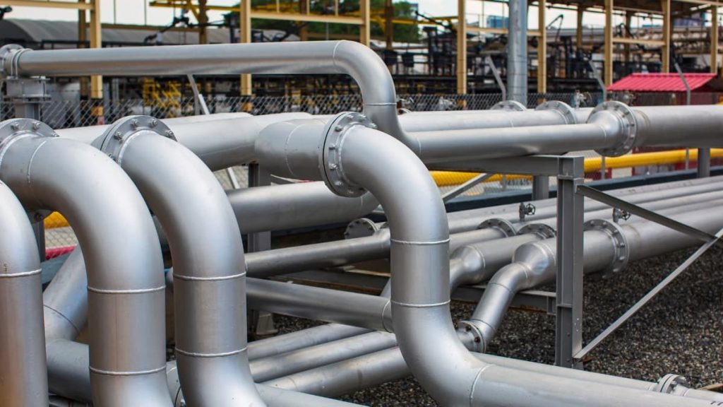
Thermal Expansion in Piping Systems: Design Mistakes to Avoid Home / Learning Thermal expansion is a critical factor in the design and performance of any piping system. Pipelines carry high-temperature fluids, naturally expand and contract. If the expansion and contraction of the pipes (caused by changes in temperature) are not considered during the design of the system, it can cause major problems— – Cracks in the pipes – Leaks at the joints (connections) – Or even the entire piping system failing to work properly. At MECS Engineering, our team of Professional Engineering Consultants helps industries prevent these issues through expert planning and Piping Stress Analysis. In today’s blog, we’ll see the most common design mistakes and their solutions. Mistake 1: Ignoring Thermal Movement in the Design Phase One of the biggest errors in piping system design is failing to allow for thermal expansion. Pipes need space to expand and move. If the design doesn’t allow pipes to safely handle temperature changes, the pressure inside them will grow and cause damage later on. Solution: Use detailed Piping Stress Analysis early in the design phase. Calculate expected expansion and plan accordingly. Mistake 2: Incorrect Placement of Expansion Joints Expansion joints are special parts added to a piping system to handle movement caused by temperature changes (like expansion or contraction). Poor positioning or misalignment may cause stress. And, shift to the other parts of the system. Solution: Engage Professional Engineering Consultants to accurately plan expansion joint placement based on pipe layout, temperature range, and support structures. Mistake 3: Using Rigid Supports for Expanding Pipes Rigid anchors and supports can restrict pipe movement. When thermal expansion is forced against these hard stops, it results in stress points that lead to cracks or leaks. Solution: Use a combination of smart supports that let the pipes move a little when needed. Keep everything strong and in-place. Mistake 4: Overlook Operational Changes Some engineers design based only on the initial operating conditions. They do not consider future temperature changes or equipment upgrades. Solution: Choose an experienced provider of Industrial Engineering Services like MECS Engineering to build flexibility into your system for future-proof performance. CONCLUSION Thermal Expansion is unavoidable. But we can plan for it so that it doesn’t cause any damage. By investing in expert Piping Stress Analysis and working with qualified Professional Engineering Consultants, you can reduce costly repairs. You can also ensure system longevity. At MECS Engineering, we offer advanced Industrial Engineering Services tailored to complex piping systems across industries. Visit us today for smart & stress-free solutions.
Top Challenges in Piping Engineering and How FEA Solves Them
![Professional Engineering Consultants, engineering consulting firms, engineering services, engineering project management, engineering consultancy, engineering consulting, civil engineering consulting, civil engineering services, structural engineering consulting, structural engineering firms, industrial engineering consulting, industrial engineering solutions, environmental engineering consulting, mechanical engineering firms, aerospace engineering consulting, geotechnical engineering services, best structural engineering firm in [city], affordable civil engineering consultants for small projects](https://mecsengineering.com/wp-content/uploads/2025/08/Untitled-design-8-1024x683.jpg)
Top Challenges in Piping Engineering and How FEA Solves Them Home / Learning One of the most important fields in contemporary industrial design, piping engineering ensures that pipelines are safe to carry fluids under any conditions. Despite multiple challenges facing the industry like design complexity, safety issues, and international code compliance, Finite Element Analysis (FEA) steps into the scene as an ace. For any piping engineering company, an integration of FEA with Stress Analysis, Third-Party Verification, and P.Eng./P.E. Certification ensures reliability and compliance at each step. Understanding the Essence of Piping Engineering Piping engineering is concerned with designing, analyzing, and maintaining pipelines that carry liquids, gases, or slurries in the oil & gas, petrochemical, and power generation industries. Designers and analysts need to keep in mind: High-pressure operations Temperature variation Corrosion and material degradation Seismic and environmental conditions Stringent industry regulations Unless proper analysis and code compliance are done, piping failures can result in catastrophic accidents, financial loss, and legal consequences. Key Challenges in Piping Engineering Complex Stress Analysis Pipes are subjected to various types of stresses, thermal, pressure, and external loads. Conventional techniques seldom manage to quantify the nuances of these complexities. Material Selection & Longevity Selecting an appropriate material that resists elevated temperature, corrosion, and fatigue is perhaps the most challenging task for piping engineers. Adherence to International Standards Compliance with ASME, CSA, and ISO codes usually necessitates Third-Party Verification and P.Eng. Certification to ensure engineering reports are certified. Risk of System Failures Leaks, bursts, and vibration problems create operational and safety hazards when not discovered during the design phase. Documentation & Certification Authorities and customers require stamped engineering reports with P.Eng. Stamping or P.E. Certification to guarantee safety and responsibility. What a Finite Element Analysis (FEA) Overcomes These Obstacles? Advanced Stress Analysis Finite Element Analysis (FEA) breaks down complex piping systems into smaller elements and makes it possible for engineers to conduct precise stress analysis on load conditions. This enhances forecasting and minimizes the occurrence of failures. Optimized Material Utilization Through temperature, vibration, and corrosion simulation effects, FEA makes it easy to select cost-effective yet long-lasting materials, prolonging the life of piping systems. Code Compliance & Third-Party Verification FEA reports, when accompanied by Third Party Verification, are in line with industry codes and regulations. A reputable piping engineering firm assures that designs are certified using P.Eng. Certification or P.E. Certification for operational approval. Failure Prevention By simulating extreme conditions (earthquakes, pressure surge, high temperature), FEA identifies weak spots and offers solutions prior to physical application. Certified Engineering Reports Customers are issued professionally stamped reports i.e. P.Eng. Stamping and P.E. Certification, guaranteeing the design is safe and approved for use. Benefits of Integrating FEA with Piping Engineering Improved Safety: Lower risk of leaks, bursts, or catastrophic failures. Cost Economy: Optimized material selection and less downtime. Faster Approvals: Seamless compliance with regulatory codes. Global Credibility: Stamped reports with P.Eng. Certification and P.E. Certification. Trust & Transparency: Independent Third-Party Verification increases confidence with stakeholders. Why Select a Professional Piping Engineering Firm? Utilizing an experienced piping engineering firm guarantees each project is supported by experience in Finite Element Analysis, Stress Analysis, and Third-Party Verification. Furthermore, qualified engineers add P.Eng. Stamping and P.E. Certification, which are required for regulatory and client acceptance. Conclusion Piping engineering is complex, but with Finite Element Analysis (FEA), certified stress analysis, and Third-party verification, companies can eliminate risks and ensure compliance from the start. Partnering with a qualified engineering firm provides the technical rigor, certification, and credibility needed to deliver secure, cost-effective, and globally accepted piping systems.
Piping Stress Analysis Services by MECS Engineering Inc.: Accuracy You Can Trust

Piping Stress Analysis Services by MECS Engineering Inc.: Accuracy You Can Trust </h1 > Home / Learning When you walk through a refinery, a chemical plant, or even a power station, you’ll notice miles of pipes running in every direction. These pipes carry steam, water, oil, chemicals, and gases all under pressure, at different temperatures, and often around the clock. Now imagine what would happen if just one of those pipes failed. The cost, the downtime, the safety risks… it could be huge. That’s why Piping Stress Analysis is so important. At MECS Engineering Inc., we take this responsibility seriously. Our team of experts ensures every piping system we work on is safe, reliable, and built to perform under real-world conditions. What Exactly is Piping Stress Analysis? Think of a pipe like a long, flexible straw. When hot liquid flows through it, it expands. When it cools, it contracts. If it bends too far or gets pushed too hard, it can crack. That’s basically what Piping Stress Analysis is all about: understanding how pipes will react to heat, pressure, movement, and weight. Instead of waiting for a problem to happen, engineers run tests and simulations ahead of time to spot weak points and prevent failures. It’s not about making things complicated. It’s about making sure the system works safely today, tomorrow, and years down the line. Why It Really Matters? A lot of people think pipes are just simple metal tubes. But in industries like oil & gas or power generation, they’re the backbone of the whole operation. Here’s why stress analysis is non-negotiable: Safety above all – Nobody wants leaks, bursts, or dangerous accidents. Money saved – Spotting a problem early is far cheaper than dealing with a breakdown later. Smooth operations – Well-designed systems mean fewer interruptions and better performance. Meeting the rules – Industry codes and regulations demand accurate stress analysis. In short, having a skilled stress analysis engineer on the job means peace of mind for everyone involved. The Human Side of a Stress Analysis Engineer Behind every report and calculation, there’s an engineer who cares about getting it right. A stress analysis engineer isn’t just crunching numbers; they’re problem solvers. Here’s what they typically do: Look over the piping layout and spot tricky areas. Run computer simulations to see how the system reacts under pressure and heat. Recommend small but powerful fixes – maybe adding a support, changing a bend, or adjusting materials. Help project managers feel confident their system will hold up when it’s needed most. At MECS Engineering Inc., our engineers are known not just for their technical skills, but also for being approachable and practical. They don’t just hand over a report – they explain the “why” behind it, in plain language. Who Needs Stress Analysis? The truth is, nearly every industry that depends on piping needs it. A few examples: Oil & Gas – Long pipelines under extreme pressure. Chemical Plants – Where leaks can be dangerous and costly. Power Plants – Steam and water lines that never stop running. Pharma & Food – Clean, safe systems that meet strict hygiene standards. Different industries, same goal: making sure the system is reliable. And that always starts with good Stress Analysis. What Makes MECS Engineering Inc. Different? Lots of firms claim they can handle stress analysis. But at MECS Engineering Inc., accuracy is more than a buzzword — it’s our standard. Here’s how we stand out: Real experience – We’ve handled projects in multiple industries and understand their unique challenges. Modern tools – Our software and methods are designed for accuracy. Practical advice – We don’t just give theory; we offer real, usable solutions. Partnership approach – Clients trust us because we listen, explain, and collaborate. We know that every project is different, and we tailor our work to fit exactly what you need. The Benefits of Doing It Right When you choose professionals for Piping Stress Analysis, here’s what you really gain: Less worry about accidents or shutdowns. Systems that run smoother and last longer. Lower repair costs over the years. Confidence that your system meets all standards. It’s about protecting your people, your plant, and your bottom line. Real Examples, Real Value Picture a refinery where heat expansion causes a pipe to push against a wall. Without stress analysis, that pressure could cause a dangerous leak. But with the right adjustments, the system stays safe. Or think of a power plant where pipes carry steam 24/7. Proper analysis means fewer breakdowns, which means more consistent power supply. These aren’t “what-ifs.” They’re real scenarios where Stress Analysis makes all the difference. Why Partner With Us? At MECS Engineering Inc., we don’t just run calculations — we build trust. We make sure you know your piping system is ready to handle whatever comes its way. Our team blends technical expertise with a human touch. We’re approachable, reliable, and always focused on delivering solutions that work in the real world. Final Thoughts Piping might not always get the spotlight, but without it, industries would grind to a halt. That’s why Piping Stress Analysis is so important. It keeps systems safe, efficient, and reliable. With the help of a skilled stress analysis engineer, companies can avoid costly surprises and keep things running smoothly. And with MECS Engineering Inc., you can count on accuracy, expertise, and a partner who truly cares about your success.
How MECS Engineering Leads in Pipe Stress Analysis and 3D Piping Design

How MECS Engineering Leads in Pipe Stress Analysis and 3D Piping Design Home / Learning In complex engineering projects across Canada, the USA, and beyond, precision and regulatory compliance are non-negotiable. That’s why MECS Engineering is a trusted partner for high-quality pipe stress analysis and 3D piping modeling services. Backed by a team of Professional Engineers licensed in multiple Canadian provinces and several U.S. states, and with deep experience in P.Eng. / P.E. certification and CRN registration, MECS delivers reliable, compliant, and efficient engineering solutions tailored to the demands of modern industry. Expertise That Delivers Results : MECS as Professional Engineering Consultants MECS Engineering brings together a highly experienced team of Professional Engineers specializing in industrial engineering services. Every project we undertake is led by licensed professionals with P.Eng. (Canada) or P.E. (USA) credentials, ensuring full compliance, accountability, and technical integrity. Our team delivers tailored engineering solutions across a range of industries, including oil & gas, hydrogen, renewables, chemical processing, water treatment, and industrial utilities. With a deep understanding of code compliance and real-world constraints, we provide practical, efficient, and scalable designs to meet your project’s unique needs. Why Pipe Stress Analysis is Critical in Engineering Projects Across Canada, the USA, and Beyond Figuring out pipe stress is super important for making sure piping systems are safe and work well. Whether for refineries, power plants, chemical facilities, or hydrogen infrastructure, properly accounting for pressure, temperature, seismic, and mechanical loads is essential to avoid failures, downtime, and costly redesigns. At MECS Engineering, we perform high-quality pipe stress analysis using industry-standard software such as CAESAR II and AutoPIPE. Our engineers check stress, movement, support designs, and nozzle loads to make sure everything meets requirements and lasts a long time. We design and validate systems to meet ASME B31.1, B31.3, B31.5, and other relevant codes, and provide P.Eng. certification (Canada) and P.E. stamping (USA) as required by local jurisdictions or client specifications. Whether you need support in Ontario, Alberta, Texas, or internationally, MECS Engineering provides reliable, code-compliant, and professionally certified pipe stress analysis services tailored to your project. In-depth 3D Piping Modeling Services From Design to commissioning, MECS Engineering delivers intelligent 3D piping models that enhance visualization, reduce design errors, and streamline fabrication workflows. The models support clash detection, material takeoffs, and accurate support layouts, enabling smoother integration across disciplines. All 3D models are developed in accordance with the project-specific requirements, supporting faster regulatory reviews, clearer communication with stakeholders, and more efficient implementation in the field. CRN Certification and Regulatory Compliance MECS has extensive experience in CRN Number applications and Canadian Registration Number compliance for pressure vessels, piping systems, and fittings across all provinces and territories in Canada. We manage the entire CRN process—from preparing code-compliant drawings and calculations to handling submissions, regulator coordination, and revisions—ensuring a faster, smoother approval process. Whether you require P.Eng. stamping (Canada) or P.E. certification (USA), MECS delivers professional engineering services that meet provincial and territorial compliance standards, giving you confidence in every step of your project. Canada’s Trusted Partner Across the Piping Industry From Alberta to Ontario, MECS Engineering is recognized for delivering high-quality, code-compliant solutions for piping systems across Canada and beyond. We support EPC firms, fabricators, and plant owners with comprehensive engineering services—including design documentation, and P.Eng. certification—tailored to meet both project requirements and regulatory demands. Our diverse clientele spans industries such as oil & gas, chemical, hydrogen, power generation, and water treatment—each requiring the precision, reliability, and regulatory expertise that MECS is known for. What Defines MECS Engineering Deep domain expertise backed by Certified Professional Engineering Consultants End-to-end support for CRN (Canadian Registration Number) applications Turnkey solutions for pipe stress analysis across various industries High-precision 3D piping modeling for design clarity and constructability Projects professionally certified with P.Eng. stamps (Canada) or P.E. stamps (USA) In-depth knowledge of Canadian piping codes and standards Priority support for expedited CRN submissions and regulator follow-ups If you’re launching a new piping project or require professional assistance with stress analysis, CRN registration, or 3D modeling, MECS Engineering is your go-to partner. Contact us today for certified engineering services that meet Canadian standards and consistently exceed expectations.
