Thermal Stress Analysis in Piping Systems for Steam Application
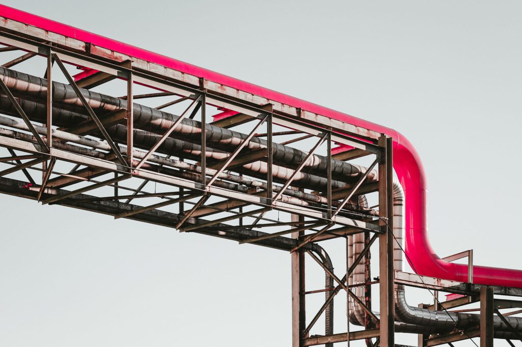
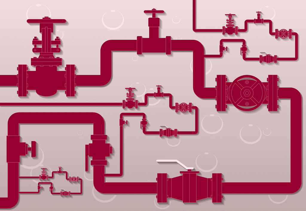
Thermal Stress Analysis in Piping Systems for Steam Application Home / Learning Steam piping plays a key role in power generation, heating systems and various industrial processes. High-pressure, high-temperature steam piping, especially for superheated steam, is critical to plant functionality and must be designed with care to handle the operational demands. Given the significant forces involved, stress analysis of these steam pipes is essential to ensure that the piping system remains safe, reliable, and operational over time. This article explores the key factors in thermal stress analysis, the mechanisms of thermal stress generation, and effective approaches to ensuring the reliability of piping systems in superheated steam environments. Superheated Steam is steam that has been heated above its boiling point at a given pressure, making it a “dry” steam without any water content. This type of steam is commonly used in industrial processes because of its higher energy content, which makes it ideal for applications like power generation where heat transfer efficiency is crucial. In a Superheated Steam Piping System, pipes are engineered to carry steam at both high temperatures and high pressures. This environment creates demanding conditions for the piping material, making robust engineering designs necessary to prevent failures. The piping must withstand thermal expansion, pressure fluctuations, and the potential for dynamic forces caused by flow conditions and operational shifts. With the intense temperatures and pressures in superheated steam systems, the risk of thermal stress becomes a critical factor in piping design. Thermal stress analysis is a key engineering process that examines how much stress and strain a pipe can tolerate before it risks failure. Since temperature variations can cause expansion, contraction, and pressure changes in the piping, thorough stress analysis ensures that all components are designed for longevity and safety. During the design stage, pipe stress analysis calculates the load that each segment of the pipe and its supports will experience. Ensuring that the piping system remains within allowable stress limits is essential to avoid any permanent deformations, such as buckling or bending, which could lead to system collapse. Codes such as ASME B31.3 provide guidelines for stress limits and other parameters for pressurized piping systems, making it a primary reference for designing superheated steam pipes. Thermal stress analysis plays a crucial role in the design and operation of superheated steam piping systems. The goal of this analysis is to identify and mitigate potential stress-related issues before they can impact the system’s performance or safety. To achieve this, engineers utilize specialized software tools like CAESAR II to simulate the behaviour of the piping system under various operating conditions. By inputting parameters such as temperature, pressure, material properties, and system geometry, engineers can generate detailed models that illustrate stress distribution across the system. This approach helps in predicting how the piping will react to thermal and mechanical forces, enabling proactive adjustments in design, material selection, and support placement. Factors in Stress Analysis of Steam Pipes Several types of stresses are examined in steam piping systems, each affecting the overall integrity of the system: 1. Primary Stresses: These are stresses resulting from sustained loads, such as internal pressure and pipe weight. Primary stresses are not self-limiting, meaning if they exceed the material’s yield strength, they could cause deformation and even rupture. 2. Secondary Stresses: Secondary stresses result from thermal movements, such as expansion and contraction, as well as constraints from supports or anchors. These stresses are self-limiting; when they exceed the yield strength, they cause local deformation that redistributes the load. However, in cyclic loading conditions, secondary stresses can become a source of fatigue failure. 3. Thermal Expansion and Sustained Loads: The high temperatures in superheated steam systems lead to thermal expansion, necessitating pipe supports and anchors to absorb these stresses. A well-designed support system helps control both thermal and sustained loads (such as the pipe’s weight and contents) without exceeding the pipe’s stress limits. 4. Pipe Support Selection: Support types and placement are fundamental to managing stress in steam piping. Supports must withstand various load types, including thermal, sustained, and sometimes external loads like wind or seismic forces. Engineers carefully select the support type, such as hangers, guides, and anchors, to balance flexibility and restraint, ensuring that the piping system can accommodate movement without compromising stability. 5. Wind Loads: In outdoor settings, wind loads on pipes can introduce additional stresses. This uniformly distributed load along the pipe length is calculated based on wind speed and supports must be adjusted to handle these dynamic forces. The Process of Pipe Stress Analysis Piping stress analysis often uses specialized software, such as CAESAR II, to simulate how the piping will respond under various conditions. Engineers model the piping system, input key parameters (temperature, pressure, pipe material), select support types, and define load cases to be analyzed. This process provides insights into stress concentrations across the pipe, allowing engineers to identify nodes with the highest stress and adjust the design accordingly. Common Load Cases in Stress Analysis of Steam Piping Several load cases are typically considered during stress analysis to ensure the piping system can withstand the various stresses it will encounter throughout its operational life. These load cases simulate real-world conditions that the piping will experience, allowing engineers to assess the system’s response and make necessary design improvements. Key load cases in stress analysis include: Expansion Load Conditions: Expansion load conditions evaluate how thermal expansion and contraction of the piping system will affect its stress profile. This load case is particularly focused on areas where temperature fluctuations are most significant, such as pipe bends, elbows, or other regions where the pipe experiences changes in direction. Thermal Expansion Effects: As steam temperature increases, the piping expands. Expansion loads are typically highest in areas where the temperature differential is greatest, such as at the entry points to boilers or turbines. Expansion-induced stresses can result in excessive bending, displacement, or even rupture if not adequately managed. To prevent stress concentrations and failure, expansion loops, flexible joints, or sliding supports are often incorporated into the system design. Stress Concentration Management: In regions where temperature changes are most extreme, stress concentrations
Canadian CRN Registration: Top 5 Pitfalls and How to Avoid Them
Canadian CRN Registration: Top 5 Pitfalls and How to Avoid Them Home / Learning Navigating the CRN process comes with certain challenges, and common mistakes can lead to delays and/or non-compliance. The stakes are high, as non-compliance can impact timelines, safety standards, and ultimately the success of your project. In this article we have highlighted top five common mistakes in CRN registration and how to avoid them. 1. Incomplete or Inaccurate Documentation Incomplete or inaccurate documentation remains one of the leading causes of delays, revisions, and rejections in Canadian Registration Number (CRN) applications. This step forms the foundation of the entire process, as it provides regulators with the information needed to validate that the equipment / system design meets the safety and compliance standards. Failing to meet these requirements can result in significant setbacks, delays and additional costs. 1.1 Engineering DrawingsDrawings visually represent the equipment or piping system, including schematics, P&IDs, layout, dimensions, welding details, and material specifications. Drawings must be up-to-date and clearly annotated to avoid delays. 1.2 Detailed CalculationsCalculations demonstrate compliance with design codes to address critical factors such as stress analysis and safety margins. Errors or omissions in these calculations can lead to rejections. 1.3 Material SpecificationsRegulators require traceable certifications for all materials used. Missing certifications or using materials not listed in the relevant codes may complicate approvals. Material data sheets must clearly specify grades, properties, and compliance to avoid unnecessary questions. Recently, we handled a registration for a special fitting where a non-code material was used by our client. Although we submitted all the available information with the application, the use of a special material with no published standards required multiple rounds of discussions with the regulators. This was necessary to ensure the surveyor was fully satisfied with the provided information. 1.4 Code Compliance ReportsThese reports link the design to specific provisions in applicable codes, ensuring adherence to safety and construction standards. Missing supplementary details, such as stress analysis, fatigue or impact analysis, can cause delays in approval. Cross-reference of documentation with provincial requirements and consulting a professional engineer is helpful to ensure all data is accurate and aligned with the relevant codes.Lorem ipsum dolor sit amet, consectetur adipiscing elit. Ut elit tellus, luctus nec ullamcorper mattis, pulvinar dapibus leo. 2. Misinterpreting Provincial and Territorial Requirements While CRN registration is governed by Canadian laws, each province and territory in Canada has its own unique interpretations and specific requirements for the process. The consequences of misinterpreting these regional differences include delayed reviews, increased costs from resubmissions, and potential rejections requiring significant revisions. To avoid these pitfalls, it is essential to research the specific requirements of the jurisdiction where the application is being submitted. Provincial regulator websites or technical guidelines are valuable resources. Working with experts familiar with local regulations ensures that applications are tailored to meet all necessary criteria, streamlining the approval process. 3. Ignoring Multijurisdictional Registration Needs Another common misconception about CRN registration is that once a design is registered in one province, it automatically applies nationwide. This is not the case, particularly when equipment is intended for use across multiple provinces. Design changes or updates often require re-submission and approval in each jurisdiction. Administrative requirements can also present challenges. For example, in Alberta, the Alberta Boilers Safety Association (ABSA) allows the use of a simplified version of the Statutory Declaration form (AB-351), which does not require notarization. However, other provinces do not accept this format. We recently encountered this issue while registering a design for Alberta. To avoid such surprises, it is essential to plan ahead for multijurisdictional registrations and ensure that any design changes are submitted for approval in each relevant province. 4. Skipping Comprehensive Design Reviews Thorough internal reviews are critical before submitting a CRN application. Overlooking minor details can lead to design flaws being flagged during regulatory reviews, which can delay the approval process. Common Pitfalls: Inadequate analysis or failure to meet the latest ASME or CSA code requirements. Missing the code edition date, which is a very common mistake in our experience. Overlooking safety margins or other critical design considerations. Engaging a qualified professional engineer (P.Eng.) to conduct a detailed review of your design, will ensure that it meets all regulatory requirements. 5. Mismanagement of Indemnification and Ownership Responsibilities Improperly proposed NDAs may attempt to shift the responsibility for design quality and performance to engineers or consultants, rather than the actual owners of the pressure equipment. Understanding Ownership: Owners (manufacturers, distributors, sellers, or end-users) are ultimately responsible for the equipment’s performance and safety. Engineers provide recommendations but cannot assume liability for operational issues outside their scope. It is advised to clearly define indemnification clauses in NDAs to ensure they reflect statutory obligations. Ensure ownership responsibilities are not inappropriately reassigned to parties without control over the equipment. Conclusion Proactively addressing potential challenges in the CRN application process can help companies avoid delays and added costs. At MECS Engineering, we provide third-party verification services and CRN registration support to ensure your pressure equipment and piping systems comply with all regulatory requirements. With our expertise, we help streamline the registration process, minimize errors, and ensure compliance with the necessary standards for efficient approvals.
Comprehensive Stress Analysis for Pressure Safety Valve (PSV) Piping Systems: Ensuring Safety and Compliance

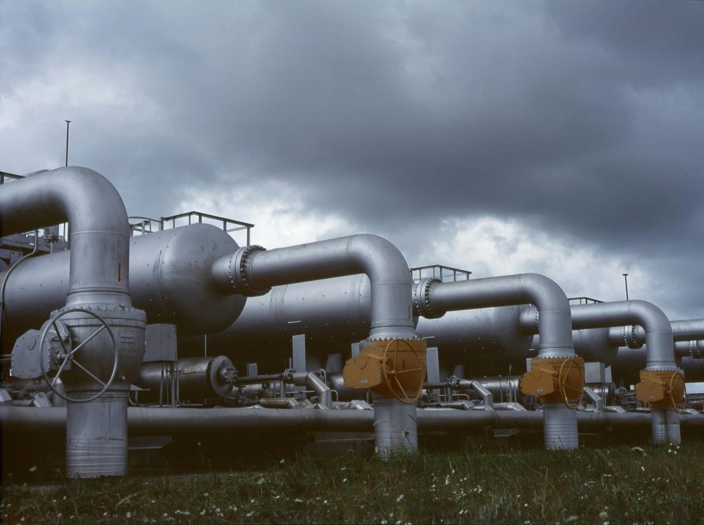
Comprehensive Stress Analysis for Pressure Safety Valve (PSV) Piping Systems: Ensuring Safety and Compliance Home / Learning In industrial piping systems, controlling pressure within safe limits is vital to prevent hazardous over-pressurization. Pressure Safety Valves (PSVs) are crucial in this regard, as they are designed to release pressure once it reaches a pre-set limit, protecting equipment, the surrounding environment, and personnel from potential harm. However, when a PSV activates, it exerts dynamic forces on the connected piping, creating stress-critical conditions. Therefore, a thorough stress analysis of PSV-connected piping systems is essential for both safety and compliance. This article provides an in-depth look at the stress analysis of PSV systems, from the fundamental PSV types and discharge classifications to the load cases needed for accurate modeling. Understanding the critical loads and forces involved enables engineers to design safer, more reliable systems that meet industry standards. Types of PSV Discharge Systems: Open vs. Closed Discharge The two primary PSV discharge systems—open discharge and closed discharge—handle fluid forces differently: Open Discharge: In this system, the PSV discharges directly into the atmosphere. This approach is often used for non-toxic or non-flammable gases, where environmental and safety risks are minimal. Closed Discharge: Here, the fluid from the PSV is directed to a closed system, such as a discharge header or drum, where it can be collected for disposal or recycling. This system is typically employed for hazardous or high-value fluids that require containment. Each discharge type imposes distinct forces on the piping, which must be accounted for during stress analysis to ensure stability and prevent failures under relief conditions. Design Principles for Pressure Relief Devices The key principle behind pressure relief devices is intrinsic safety; they must either “fail safe” or not fail at all. Solutions to issues in pressure relief piping should rely on solid design practices, as any failure is unacceptable. Prioritizing simplicity and established guidelines is vital for ensuring reliability. Here are four primary reasons to approach the engineering of pressure safety valves and discharge systems with precision: Flow Capacity Restrictions: The design of inlet and outlet piping can hinder flow, potentially compromising the valve’s ability to release pressure safely. Operational Performance: Poor design can negatively influence the operation of the PSV, altering its opening or closing pressures. Risk of Mechanical Failures: The thrust generated during valve discharge can result in mechanical failures within the piping system. Safety Valve Inlet Piping :To function effectively, safety valves should be mounted vertically, either directly on the vessel nozzle or via a short connection that allows for unobstructed flow. This principle should also apply to safety valves safeguarding piping systems. Pressure Drop:The pressure drop between the vessel and the safety valve inlet should be minimal to prevent starving the valve or causing it to chatter. Preventing Piping Overstress :It is crucial to avoid overstressing the inlet piping or mounting nozzle on the vessel. Consider the reaction force during valve operation along with forces from the discharge piping; minimizing the length of the inlet piping can help reduce strain. Safety Valve Discharge Piping :The allowable back-pressure on a safety valve depends on several factors, including its back-pressure rating, which may differ from the ASA rating of the outlet flange. This should be verified with the manufacturer. Conventional safety valves should not experience back-pressure exceeding 10 percent of the net setting, and it must always remain at least 5 psi lower than the opening pressure. Drain Hole Management :In applications where liquids may accumulate at the valve discharge, it’s essential to remove the drain hole plug. This applies in scenarios where condensate can form or precipitation may enter the discharge line. If the plug is removed, the drain must be piped safely for disposal, particularly if the fluid poses a hazard or if sudden discharges could endanger personnel. Piping Support Design Safety valves need to measure pressure within a 3% accuracy and fulfill specific control functions. Excessive strain on the valve body can hinder its performance. Therefore, piping supports should be designed to minimize load on the valve. In high-temperature applications, excessive loads can cause permanent deformation, and even at lower temperatures, distortion may result in leaks below the set pressure. Discharge piping should be supported independently from the valve and carefully aligned to reduce forces during normal operation. Properly designed expansion joints or long-radius bends should be included to prevent excessive strain. Discharge Piping Stress Analysis is mainly subjected to stresses from thermal expansion and discharge reaction forces. The rapid release of compressible fluids can create impact loads and bourdon effects at directional changes, necessitating adequate anchoring to prevent sway or vibration during discharge. Minimizing Pressure Loss To limit pressure loss in discharge piping, the system should be as direct as possible, employing long-radius bends and avoiding tight-fitting connections. The discharge pipe’s cross-sectional area must never be smaller than that of the valve outlet. Main Load Cases for PSV Stress Analysis Effective PSV stress analysis involves defining load cases that accurately capture the operational and occasional forces exerted on the system. Below are essential load cases typically evaluated for PSV piping systems: Sustained Load Case (Operating Condition): This load case models sustained forces that occur under normal operating conditions, including: Weight (W): Accounts for the weight of the piping, insulation, and fluid. Internal Pressure (P): The pressure within the piping during standard operation. Thermal Load Case (Expansion): Thermal expansion or contraction occurs as the piping temperature changes. It is essential to account for this to prevent excessive stress during temperature fluctuations. Key Component: Thermal Expansion (T1): Thermal forces associated with the operating temperature. Occasional Load Case (Relief Scenario): During PSV activation, sudden pressure release generates dynamic jet forces, which classify as occasional loads. These forces need to be considered along with sustained loads to simulate a PSV relief event. Key Component: Relief Reaction Forces (F): Resulting from the rapid release of gas or liquid. Thermal Expansion with Relief Forces: If the PSV is triggered while the system operates at high
Piping Design and Stress Analysis for Hydrogen Pipelines: A Technical Perspective

Piping Design and Stress Analysis for Hydrogen Pipelines: A Technical Perspective Home / Learning As hydrogen becomes an increasingly important energy carrier in the global push for clean energy, the design and analysis of hydrogen pipelines are paramount to ensuring both efficiency and safety. Hydrogen poses unique challenges to piping systems due to its low molecular weight, high diffusivity, and flammability. These characteristics necessitate advanced piping design principles and stress analysis techniques to minimize risks such as leaks, embrittlement, and system failure. MECS Engineering is at the forefront of addressing these challenges by applying cutting-edge methodologies for piping stress analysis and design tailored for hydrogen transportation. The Challenges of Hydrogen Pipelines Hydrogen is highly volatile and flammable, requiring careful design to prevent hazards when transported through pipelines. Hydrogen’s small molecular size makes it prone to diffusion through materials, increasing the risk of leaks. It can cause embrittlement in certain materials, which increases the likelihood of fractures and leaks. It often operates under high pressures, necessitating durable pipeline design to ensure structural integrity and safety. Due to the unique characteristics of hydrogen, effective stress management is crucial to maintain the pipeline’s operational efficiency and prevent failure. Stress analysis is vital in ensuring that the pipeline can withstand the stresses induced by hydrogen flow without compromising safety or structural integrity. Codes and Regulatory Compliance: ASME B31 series encompasses ASME B31.12 code dedicated to hydrogen piping systems. It covers the specific challenges posed by Hydrogen and provides essential guidelines for the design, construction and maintenance of hydrogen pipelines, covering factors like material selection, pressure ratings, and safety measures. In conclusion, this article has explored the common causes of pipe failures in industrial plants, emphasizing the critical role of stress analysis in preventing such failures. By identifying weak points, ensuring safety, optimizing design, and maintaining compliance with industry standards, stress analysis serves as a cornerstone in achieving reliable and efficient piping systems. At MECS Engineering, we specialize in piping stress analysis to help clients protect the integrity of their piping systems. Our team of expert engineers ensures that your systems are designed to withstand operational stresses, reduce costs, and meet all safety and regulatory requirements. Key Considerations in Piping Design for Hydrogen Pipelines 1. Material Selection Material selection is one of the most critical factors in hydrogen pipeline design. To prevent the cracks and fractures, materials with high resistance to hydrogen embrittlement are selected, including: Stainless Steel (300 series): Stainless steel is commonly used for hydrogen pipelines due to its resistance to hydrogen embrittlement and its high strength. However, material selection must take into account hydrogen pressure and temperature conditions, as hydrogen can cause embrittlement at higher pressures. High-Strength Low-Alloy (HSLA) Steel: HSLA steels are used when high strength is required for pipeline construction. These materials offer good resistance to hydrogen-induced cracking (HIC). Composite Materials: Materials such as fiberglass and carbon fiber composites may also be used in some applications to prevent hydrogen permeation while offering lightweight solutions. 2. Wall Thickness Design The wall thickness of hydrogen pipelines is crucial in managing internal pressures, stresses, and the effects of hydrogen embrittlement. According to the ASME B31.12 code, the pressure design thickness must account for both the internal pressure and the material’s susceptibility to hydrogen. In particular, the following considerations are essential: Internal Pressure: Hydrogen pipelines often operate under high pressure (up to 1500 bar in some cases), which necessitates thick walls to withstand the mechanical stresses. The design must ensure that the material selected can resist these pressures without failure. Hydrogen Effects: Hydrogen-induced stress must be factored into the thickness calculation, as it can significantly affect material properties. The Mf factor is applied to adjust for the ductility reduction in metals due to hydrogen exposure, effectively increasing the required thickness. 3. Stress Analysis for Hydrogen Pipelines Piping Stress analysis is essential to ensure that the pipeline can withstand both mechanical and thermal stresses while maintaining safety. The unique properties of hydrogen introduce specific factors that must be considered in the stress analysis: Thermal Stress: Hydrogen pipelines can experience significant temperature fluctuations depending on the phase (gas or liquid) and transport conditions. Thermal expansion and contraction in pipelines can induce stress at joints and bends, which needs to be carefully calculated. Dynamic Loading: Hydrogen pipelines design can also experience dynamic loads due to flow fluctuations, temperature variations, or external forces such as seismic activity or thermal cycling. The stress analysis must factor in these dynamic loads to ensure the system remains intact over time. Fatigue and Fracture Mechanics: Hydrogen embrittlement is a particular concern when performing fatigue analysis. Materials that are exposed to hydrogen may fail earlier than expected under cyclic loading. The ASME B31.12 code provides guidelines to account for this and helps identify potential fracture points in the system. MECS Engineering utilizes advanced stress analysis software to model these factors and also applying finite element analysis (FEA) to simulate the pipeline’s behavior under various conditions. This enables precise calculations for stresses at different locations and provides valuable insight into potential weak points in the design. 4. Leak Detection and Prevention Given hydrogen’s flammability and small molecular size, leak detection and prevention are critical aspects of the Hydrogen piping design process. The following design features are incorporated to minimize the risk of hydrogen leaks: Leak-Free Joints: Piping joints must be carefully designed to ensure leak-tightness. Welding is typically the preferred method for creating joints in hydrogen pipelines, as it provides superior sealing properties compared to mechanical joints. Sealing Technologies: Advanced sealing materials such as elastomers and fluoropolymers are often used in hydrogen pipeline systems to prevent leaks. These materials are chosen for their resistance to permeation and ability to maintain flexibility in extreme conditions. 5. Design for Seismic and External Loads Hydrogen pipelines, especially those that span large distances or are located in seismic zones, need to be designed to withstand external loads, including seismic activity, soil movements, and other environmental factors. The following considerations are essential: Seismic Analysis: In regions
Top 5 Reasons for Piping Failures and the Importance of Stress Analysis for prevention

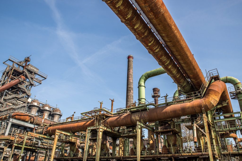
Top 5 Reasons for Piping Failures and the Importance of Stress Analysis for prevention Home / Learning Piping systems are critical to various industries, including power, oil and gas, water treatment, chemical processing, HVAC, and other process industries. Despite their importance, these systems have been associated with numerous reliability and safety incidents. Ensuring their reliability, integrity, and safety demands rigorous analysis. A variety of factors contribute to pipe failures, ranging from material degradation to design flaws. Such failures can result in significant costs, including expensive repairs, unplanned production downtime, and, in severe cases, serious safety hazards. Understanding the causes of pipe failures and the role of stress analysis is vital in preventing these issues and maintaining system reliability. Below is a comprehensive look at the common causes of pipe failures and the critical role of stress analysis in mitigating these risks. Causes of Pipe Failures 1. Lack of Stress Analysis for Various Loads: Insufficient stress analysis and inadequate piping flexibility can lead to excessive loads on the system, ultimately causing failure. Piping systems are subjected to various types of loads, including primary loads like hoop stress, secondary loads such as thermal load or displacement, sustained loads, occasional loads, and reaction or impact forces. Each of these loads affects the system’s performance, and if not properly analyzed and managed, they can lead to system failure. Below are the common loads that occur in piping systems and can cause failure if not adequately analyzed and maintained. 1.1 Principal Piping Stresses: Fluid pressure within a pipe creates three primary types of stress: Longitudinal (Axial) Stress (δa): This stress acts along the length of the pipe. In the case of a pipe sealed with caps at both ends, the longitudinal stress is exerted toward the fittings, potentially causing the fittings to detach or push the pipe ends outward. Circumferential (Hoop) Stress (δh): This stress acts outward, around the pipe’s circumference. It is the most significant stress and can cause the pipe to split along its length, especially under high pressure. Radial Stress (δr): Radial stress is exerted away from the pipe’s central axis, extending outward toward the pipe wall. It is the least significant of the three types of stress. Among these three types of stresses, hoop stress has the largest effect followed by axial stress and radial stress being the smallest.Principal or primary stresses are typically force-driven, meaning they are caused by external forces such as gravity, internal pressure, spring load, pressure safety valve operation, and water hammering. These forces can exert significant stress on piping systems, making it crucial to account for them during the design and analysis phases to ensure the system’s integrity and avoid potential failure. 1.2 Principal Piping Stresses: Sustained loads are caused by internal pressure and the weight of the piping components, including valves, flanges, and fluid, as well as additional factors like thermal insulation or snow in colder climates. These loads primarily create longitudinal or axial stress (δa) from fluid pressure. If not properly managed with adequate pipe supports, sustained loads can lead to piping failure or collapse. 1.3 Sustained Load: Sustained loads are caused by internal pressure and the weight of the piping components, including valves, flanges, and fluid, as well as additional factors like thermal insulation or snow in colder climates. These loads primarily create longitudinal or axial stress (δa) from fluid pressure. If not properly managed with adequate pipe supports, sustained loads can lead to piping failure or collapse. Earthquake and Blast Load: Forces generated by seismic events or explosions. Wind Load: Caused by sudden air movement. If not accounted for in the design, it can lead to piping failure or damage to facilities. 1.4 Displacement Stress: Displacement stress is a secondary load, like thermal stress, that fluctuates between hot and cold conditions. As the temperature changes, the allowable stress (Sc and Sh) also changes. This can cause failure if the material is exposed to a single excessive hot load or repeated cycles that exceed the allowable stress range (SA).Thermal expansion is a type of displacement stress that usually occurs with temperature fluctuations in the piping system and if the system is not flexible enough to handle these changes then it causes a leakage or pipe failure. 1.5 Piping Reaction Forces: Reaction forces in piping can result from pressure safety valves, slug flow, and water hammering. These forces, classified as dynamic loads by ASME B31.3, can cause vibration and potential damage to the piping system. Pressure Safety/Relief Valve Reaction Force: When the safety valve opens, it generates reaction forces due to back-pressure and sudden impulses, particularly in gas services with high velocity and pressure. Proper pipe support is essential to manage these forces. Slug Flow Reaction Force: Slug flow, a mixture of gas and liquid, causes vibration and load fluctuations, negatively affecting the piping system and potentially shutting down the process. Water Hammering Load: Water hammering occurs from rapid changes in flow rate, such as valve operation or pump cycling, creating pressure surges that can damage the piping. 2. Corrosion: Corrosion is a chemical reaction where metals return to their natural state, often leading to material degradation and pipe fragility. The main types of corrosion affecting piping systems include: Uniform Corrosion: Caused by exposure to moisture and oxygen, resulting in rust. Galvanic Corrosion: Occurs when dissimilar metals interact, accelerating corrosion at the joint. Pitting and Crevice Corrosion: Common in environments with acidic or chloride-containing fluids, leading to localized, deep pits. Corrosion can weaken pipes, making them prone to breakage. To mitigate corrosion risks, material selection, coatings, and cathodic protection are essential preventative measures. 3. Water Hammering: High velocity or pressure in piping systems can lead to water hammer, a phenomenon where abrupt changes in flow generate pressure waves that strike valves and pipe walls, causing loud rattling sounds and potentially damaging pipe supports, valves, and the pipes themselves. This occurs when fast-moving fluid is suddenly stopped, creating stress on the pipe walls. When a valve closes quickly, it interrupts the flow, causing water or gas
Analyzing Seismic Loads in Piping Systems for Earthquake-Prone Areas
Analyzing Seismic Loads in Piping Systems for Earthquake-Prone Areas Home / Learning In earthquake-prone regions, designing resilient piping systems is essential to ensure public safety and protect infrastructure. Seismic loads introduce unique challenges, including dynamic forces from ground movement and structural interactions between pipelines and their surroundings. A well-engineered piping system must withstand seismic stresses, maintaining functionality during and after seismic events. This article delves into the critical aspects of seismic design for piping systems, covering the methodologies, analytical techniques, and practical benefits of incorporating seismic resilience into pipeline engineering. Why Seismic Design Matters in Piping Systems Piping systems in earthquake-prone regions are vulnerable to damage due to seismic forces. The impact ranges from minor deformation to catastrophic failure, leading to hazardous leaks, equipment damage, and operational shutdowns. This risk is particularly high in safety-critical industries such as nuclear power, chemical processing, and oil and gas.To mitigate these risks, engineers use specialized seismic analysis and design methodologies to predict and accommodate the effects of ground movements. These designs factor in: Seismic hazards specific to the region. Piping system geometry and material properties. Interaction with supporting structures. Key Factors in Seismic Design Seismic analysis is influenced by several critical factors, including the natural frequencies, restraint configuration, and response spectra. Here’s an in-depth look: Piping Geometry and Restraint ConfigurationThe natural frequency of a piping system is dictated by its geometry and restraint layout. By strategically altering these elements, engineers can “tune” the system to avoid resonance and reduce seismic loads. Response SpectraResponse spectra measure how a structure, such as a building or support, amplifies ground vibrations during an earthquake. Understanding this amplification is critical for assessing the piping system’s response and designing appropriate mitigation measures. Earthquake History and Regional SeismicitySeismic design starts with an assessment of earthquake potential, based on historical seismic data. This includes analyzing previous earthquakes’ intensity, frequency, and impact, combined with geological and geotechnical studies. Methods for Seismic Analysis and Design Seismic analysis employs both static and dynamic methods, each suited to specific scenarios. The five primary techniques are: Uniform Building Code (UBC) Analysis: The UBC provides a framework for estimating seismic loads based on regional damage potential. Earthquake zones are classified as 0 (minimal risk) to 3 (high risk), and seismic coefficients (Z) are assigned accordingly. The design load is calculated using the formula: g=ZKCT Where: g = static equivalent g-factor to use for seismic design, multiples of gravity Z = seismic coefficient based on earthquake zone, equal to 0.0 for Zone 0,0.25 or Zone 1, 0.5 for Zone 2, and 1.0 for Zone 3 K = structure type constant, ranging from 0.67 to 3.0, dimensionless C = 0.05/T^(1/3), but not greater than 0.1 T = fundamental period (inverse of frequency) of structure, sec This method converts dynamic seismic forces into an equivalent static load, simplifying analysis for routine design applications. Nuclear Seismic Design: Nuclear facilities require stringent seismic designs due to the critical nature of their operations. This involves advanced modeling techniques and adherence to strict regulatory codes. The piping in these facilities undergoes comprehensive stress evaluations, ensuring it meets allowable limits even during extreme seismic events. Time History Analysis: Time history analysis uses earthquake records to simulate seismic effects on piping systems. This method involves: Plotting ground motion data (displacement, velocity, acceleration) over time for three spatial directions. Applying these data to a dynamic model of the piping system. The analysis provides detailed insights into stress, displacement, and support loads at each time step during an earthquake. Although highly accurate, this method is computationally intensive and expensive, making it ideal for critical systems in high-risk regions. Modal Analysis Using Response Spectra: Modal analysis simplifies dynamic analysis by breaking a piping system into individual vibration modes. Engineers calculate the response of each mode to seismic input and combine these to determine the total system response. Key equations include: Where, This method is cost-effective compared to time history analysis and widely used for complex piping systems. When the applied acceleration is removed from an undamped oscillator (a=0,C=0), the system continues to vibrate at its undamped natural frequency (ωnomega_nωn). This frequency is critical in assessing the dynamic response of the piping system. Applying a vibratory motion to the system can result in higher accelerations on the mass than those input at the base. This outcome depends on the interaction of velocity and displacement at specific moments during the seismic event. By examining the amplification factor, the shape of the response spectra becomes clear: Flexible Range: When the oscillator’s natural frequency is much smaller than the forcing frequency, the amplification factor approaches zero. Resonant Range: As the oscillator frequency nears the forcing frequency, the amplification factor increases significantly, resulting in two distinct peaks. Rigid Range: When the oscillator frequency is much greater than the forcing frequency, the amplification factor approaches 1.0. The acceleration matches the imposed motions, termed as zero-period acceleration. These ranges dictate the dynamic behavior of the system and highlight how seismic forces amplify or attenuate depending on frequency relationships. The total seismic response of the piping system is determined by summing the responses of its individual vibration modes. These responses depend on the natural frequencies of the system, which are influenced by its geometry and restraint configuration. By adjusting these parameters, engineers can “tune” the system to modify its natural frequencies, thereby reducing its seismic response and associated stresses. The response spectra effectively represent the interaction between the building and the piping system during an earthquake. Natural frequencies and mode shapes of the piping system are typically calculated using a lumped-mass model in computational analysis, which employs an eigenvalue-eigenvector algorithm. Static Analysis: Static analysis is employed when detailed dynamic modeling is unnecessary. It approximates seismic forces using a simplified approach. For example: Using response spectra data, engineers identify the acceleration corresponding to the system’s fundamental frequency. Multiplying this acceleration by the piping’s linear weight determines the static seismic load. This conservative method is suitable for less critical applications or systems where response spectra data
Understanding Third-Party Verification: Why It’s Essential in Engineering Projects

Understanding Third-Party Verification: Why It’s Essential in Engineering Projects Home / Learning With the engineering projects becoming more complex, third-party verification has emerged as a cornerstone for ensuring quality, regulatory adherence, and reliability. This independent assessment is essential for enhancing project integrity and transparency, where objectivity is important to meeting high standards. It covers a spectrum of critical activities—such as inspections, document reviews, and quality audits—that verify each project component meets precise industry benchmarks. Here, we explore the importance of third-party verification, its detailed processes, and the substantial benefits it brings to engineering projects. What is Third-Party Verification? Third-party verification is a process in which an independent party assesses various project facets—such as design specifications, material properties, regulatory compliance, constructability, operability, maintainability, and safety (COMS) aspects – to ensure adherence to industry standards. The neutrality of third-party verifiers eliminates potential conflicts of interest ensuring a fair and unbiased evaluation. MECS Engineering offers expert third-party verification services across industries such as Process, Power (Nuclear and Fossil), Co-Generation, Oil and Gas, Refineries, Chemical and Petrochemical, and Pharmaceutical Facilities. Key Activities in Third-Party Inspection at MECS Engineering: Third-party verification at MECS Engineering typically involves the following activities: Documentation Review: Ensuring design documents and specifications meet project and industry standards. Code Compliance Verification: Confirming adherence to codes such as ASME for engineering and safety standards. Regulatory Compliance: Verifying that designs align with applicable regulations to ensure project viability. Safety and Operability Assessment: Reviewing designs for safety and operational effectiveness. Comprehensive Reporting: Providing a detailed report with compliance findings and recommendations. Why Third-Party Verification Matters Objective Evaluation: Our independent verification ensures unbiased evaluation, free from internal project pressures. This impartiality is especially important for assessing components where project teams may have vested interests, such as financial targets or project deadlines. Compliance Assurance: Engineering projects must comply with various standards and codes. Our team at MECS Engineering possess in-depth regulatory knowledge, providing a rigorous assessment to ensure that your projects are fully compliant with local and international regulatory requirements, Risk Mitigation: Early identification of potential issues is crucial for managing risk. By detecting discrepancies and recommending improvements, our team helps in addressing risks proactively, contributing to seamless project execution. Technical Proficiency: Our team of experts, ensures that your project components are assessed by professionals knowledgeable industry leader in specific technical areas, thereby upholding project standards. In conclusion, third-party verification might sometimes appear as an extra step, but it’s essential for ensuring project quality, compliance, and long-term reliability. By providing an objective evaluation, MECS Engineering safeguards projects against oversights and elevates them to meet stringent industry standards. This independent verification reinforces project success, builds trust, and minimizes risks that could compromise quality or lead to costly rework. To discuss how MECS Engineering can add value to your projects through third-party verification, contact us at www.mecsengineering.com
Importance of Optimal Piping Layout for Efficient Stress Analysis in High-Temperature Lines
Importance of Optimal Piping Layout for Efficient Stress Analysis in High-Temperature Lines Home / Learning In industries such as oil and gas, chemical processing, and power generation, high-temperature piping systems play a crucial role in ensuring the safe and efficient transportation of fluids. However, designing these systems requires meticulous attention to thermal expansion, stress analysis, and layout considerations. A poorly designed piping layout can lead to serious issues such as excessive stresses, mechanical failures, and even system shutdowns. The optimal piping layout, especially in high-temperature lines, is essential for reducing stress, prolonging equipment life, and ensuring operational safety. Challenges of High-Temperature Piping Systems High-temperature environments introduce an additional layer of complexity to piping systems. In such conditions, metal pipes expand when exposed to heat, which, if not accounted for, can lead to significant stress-related problems like pipe rupture, material fatigue, misalignment of connected equipment and Catastrophic failures. This is where thermal expansion becomes critical. Without accounting for the temperature variations and resulting stresses, the piping system could face catastrophic failures. A well-designed piping layout is essential to managing these stresses and ensuring long-term operational stability. Stress Analysis in Piping Systems Stress analysis is the process of evaluating how various forces act on a piping system, particularly under conditions of high temperature, pressure, and external loads. In high-temperature systems, the primary source of stress is thermal expansion. When thermal expansion is restrained by supports, anchors, or adjacent equipment, it creates internal forces, leading to thermal stress. Thermal Expansion and Its Impact on Piping Systems In high-temperature systems, one of the most critical factors affecting the design and operation of the piping system is thermal expansion. As temperature increases, materials expand—a natural physical phenomenon. Conversely, in cryogenic services, materials contract as temperature decreases. This expansion or contraction can induce significant mechanical stress, especially in long pipe runs, if not adequately accounted for in the layout. Formula for Linear Thermal Expansion: The formula that describes this expansion is as follows: Δx=α×L×ΔT Where: Δx is the change in length (expansion or contraction) α is the thermal coefficient of linear expansion (a material-specific property), L is the original length of the pipe, ΔT is the change in temperature. Even small temperature increases can cause significant expansion over long piping runs, creating stress at joints, supports, and equipment connections. Therefore, understanding and managing thermal expansion is crucial to preventing excessive stress in the system. Thermal Expansion and Piping Layout The poorly planned layouts can magnify the effects of thermal expansion. For instance, a straight run of pipe with minimal support or anchorage may be more prone to thermal stresses, leading to issues such as: Cracking in the pipe material or welds, Leaks at joints due to excessive movement, Bowing or sagging in unsupported pipe sections, Damage to surrounding support structures and misalignment of equipment. How Optimal Piping Layout Reduces Stress in High-Temperature Lines Designing an effective piping layout in high-temperature applications can drastically reduce stress within the system. Here are key layout considerations for mitigating thermal expansion-related stress: Strategic Placement of Supports and Anchors: Supports and anchors serve as the backbone of a piping system, controlling movement and maintaining alignment. However, improper placement can lead to localized stress concentration. A carefully planned layout ensures: Supports: Positioned to allow pipes to expand and contract freely, avoiding sagging or bowing. Fixed supports should be limited to prevent thermal stress accumulation. Anchors: These should be placed where pipes must be restrained, yet positioned to limit stress transfer to sensitive equipment such as turbines or pumps. By using flexible guides, lateral movement can be accommodated while constraining vertical displacement, reducing stress at key points. Use of Expansion Loops : Expansion loops are critical in absorbing thermal expansion without transferring stress to the entire system. By incorporating loops or offsets in the piping layout, the pipe is free to expand and contract naturally, reducing stress concentrations. Expansion loops come in two main configurations: Horizontal Expansion Loops: These are common in long, straight piping runs, providing flexibility that reduces the risk of buckling or deformation. Vertical Loops: Effective in systems with vertical piping runs, although care must be taken to avoid drainage issues or vapor pockets. Rerouting the Pipe: Straight runs of piping are particularly prone to high thermal stresses since expansion occurs in one direction. Introducing bends and elbows into the piping layout allows expansion to be distributed more evenly across the system, reducing stress on any single component. This rerouting process makes the system inherently more flexible and better able to absorb thermal movements. Incorporating Flexible Components: In high-temperature systems, flexible components like bellows, sliding supports, and expansion joints are essential. These components absorb axial movement caused by thermal expansion, allowing the piping to move without inducing stress. However, they require precise design and maintenance to ensure they can withstand operational conditions like temperature, pressure, and flow. Key Factors in Stress Analysis for Piping Layout While optimizing the piping layout, detailed stress analysis is critical to evaluate the design’s adequacy under operational conditions. Key factors in this analysis include: Temperature Differential (ΔT): A large ΔT results in significant thermal expansion, and the system must be designed to accommodate these movements. Material Selection: Different materials have varying thermal expansion coefficients. Selecting materials suitable for the system’s operating temperature is crucial. Code Compliance: Following ASME guidelines ensures the system meets safety standards. Simplified formulas can indicate whether detailed stress analysis, using tools like CAESAR II®, is necessary. Branching and Complex Layouts: Piping systems with multiple branches or varied pipe sizes require individual evaluation of each section to ensure they can withstand thermal stresses. Benefits of an Optimized Piping Layout in Stress Analysis The piping layout directly supports stress analysis by reducing the likelihood of excessive stress buildup and improving system reliability. Here’s how: Minimizes Excessive Stress: A well-designed layout with flexible loops like C or S shapes prevents excessive strain caused by expansion and contraction. Stress analysis using tools like
Piping Engineering: Design, Analysis, and Compliance
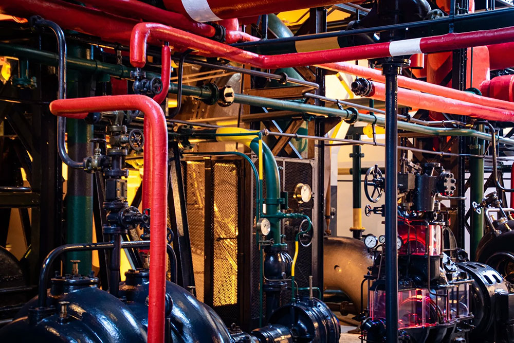
Piping Engineering: Design, Analysis, and Compliance Home / Learning Piping systems, are integral to numerous industrial processes, used to transport fluids between different locations. These systems are composed of various components, including pipes, fittings, and valves, all assembled and designed to ensure efficient and safe fluid transport. Piping engineering is the discipline that integrates material and mechanical engineering principles with specialized techniques like stress analysis and piping layout design. This comprehensive approach converts process documents, such as Piping & Instrumentation Diagrams (P&IDs) and Process Flow Diagrams (PFDs), into detailed piping drawings and data, which guide the procurement, assembly, and testing of piping systems. The Crucial Role of Piping Design The design phase of piping engineering is critical, involving the creation of plot plans, equipment layouts, and three-dimensional (3D) models that define the physical layout of the piping system. Plot Plan Development: It is a top-level drawing showing the entire facility, including equipment, buildings, and structures. It is important to ensure that site constraints, safety, and operational efficiency are considered. Proper spacing between hazardous areas, clear access routes for maintenance and emergencies, and optimal equipment positioning are key factors that contribute to reducing pipeline lengths and enhancing workflow. Equipment Layout: Detailing the position of equipment like pumps, compressors, and tanks within the plot plan is essential. Engineers ensure adequate spacing for maintenance, proper alignment to optimize fluid flow, and the inclusion of support structures for stability and accessibility. 3D Modeling Software: Advanced software tools like AutoCAD Plant 3D and PDMS allow engineers to create virtual representations of piping systems. These 3D models enable the visualization of the entire network, identification of potential clashes, and simulation of fluid flow dynamics, leading to accurate and efficient design. From these models, detailed isometric drawings and material take-offs can be generated. Piping Route and Support Design: The design of efficient piping routes minimizes pressure drops and meets process requirements. Proper support and anchoring systems are critical for managing thermal expansion, vibration, and weight, preventing sagging and stress on connections. Piping Stress Analysis to Prevent Operational Failure Piping stress analysis is a vital process that ensures the safety, reliability, and efficiency of piping systems. The analysis is the study of stresses in a piping system. It is a term applied to calculations, which addresses the static and dynamic loads such as dead weight (self-weight of the pipe including fluid, fittings and its associated components), internal and external pressure, thermal loads (due to change in temperature), seismic loads, wind loads, vibration, water hammer, stream hammer, slug force, PSV reaction force, etc. to produce a comprehensive analysis report. This process is essential to ensure that piping systems can withstand various loads during operation without compromising their structural integrity. Types of Loads in Piping Systems Piping systems are subject to several types of loads, each contributing to the overall stress experienced by the pipes: Ensuring Structural Integrity: Stress analysis evaluates the effects of thermal expansion, contraction, and other loadings on the piping system. By understanding the stress distribution and potential failure points, engineers can design piping systems that maintain structural integrity under extreme conditions. Preventing Overstress: High-temperature environments can lead to overstress in piping components, supports, and connected equipment. Stress analysis helps in optimizing the design to prevent overstress and reduce the likelihood of failures, such as cracking or rupture. Compliance with Codes and Standards: Piping systems must comply with various industry codes and standards, which specify allowable stress values, material requirements, and design considerations. Stress analysis ensures that the piping system meets these requirements, particularly in high-temperature applications where allowable stress values are reduced. Optimizing Design: While ensuring safety is paramount, overdesign can lead to unnecessary costs and inefficiencies. Stress analysis allows for the optimization of piping systems by accurately predicting stress levels and enabling the use of appropriate materials and supports without excessive safety factors. Conducting Piping Stress Analysis Piping stress analysis involves creating a detailed model of the piping system and simulating the various loads it will encounter during operation using specialized software tools. Specialized Software Tools: Engineers use software like CAESAR II, AutoPIPE, ROHR2, and PIPESTRESS to perform both static and dynamic stress analysis, model piping systems, and analyze flexibility and stress under different loads. Modeling the Piping System: The initial step involves developing a detailed model that includes all relevant components—pipes, fittings, valves, supports, and equipment connections. Key aspects are as follows:: Geometry: Accurate representation of the piping layout, including lengths, diameters, and routing. Material Properties: Incorporating the mechanical properties of the piping materials, such as Young’s modulus, Poisson’s ratio, thermal expansion coefficients, and yield strength. Boundary Conditions: Defining the constraints and supports, such as fixed supports, sliding supports, and anchors. Simulating Loads: Engineers simulate various loads, including internal pressure, thermal expansion, weight loads, external forces, and dynamic loads, to assess how the piping system will respond during operation. Internal Pressure: Simulations assess hoop, longitudinal, and radial stresses to ensure the pipe can withstand internal fluid pressure without failure. Thermal Expansion: Temperature changes cause pipes to expand or contract, with simulations helping to design expansion joints and supports that prevent stress-related issues Weight Loads: Engineers simulate the combined weight of the pipe, fluid, and insulation to ensure the support system prevents sagging or overstressing. External Forces: Simulations consider wind, seismic activity, and soil pressure to design supports and bracing that protect the system from external environmental stresses. Dynamic Loads: Transient conditions like water hammer or pump startup/shutdown are simulated to assess the system’s ability to handle sudden changes in flow or pressure. Assessing the System’s Response: The system’s response to loads is evaluated by checking for excessive deformation, comparing stress levels to code limits, and conducting fatigue analysis to identify potential failure from cyclic loading. Identifying and Mitigating Issues: If analysis reveals issues like overstress or excessive deformation, engineers take corrective actions as followed:4 Re-routing Piping: Modifying the layout to reduce stress concentrations and improve flexibility. Adding Supports: Introducing additional supports or changing the type of supports to better manage the loads. Using Expansion Joints: Incorporating expansion joints or loops to
Advanced Piping Stress Analysis for High-Temperature Services
Advanced Piping Stress Analysis for High-Temperature Services Home / Learning When piping systems are exposed to high temperatures, the physical and mechanical properties of the piping materials undergo significant changes, leading to complex challenges in maintaining system integrity and safety. This article delves into the effects of high temperatures on piping systems, the importance of stress analysis in such environments, and the techniques and tools used to perform these analyses effectively. The Impact of High Temperature on Piping System High-temperature environments have a profound impact on the behavior of piping designs. As the temperature rises, the piping material expands, leading to displacement in the system. This displacement is not uniform; instead, it can cause the piping to move vertically, axially, and laterally. The extent of these movements increases with temperature, creating additional stresses and strains within the system. Thermal Expansion and Contraction: The primary effect of temperature changes on piping systems is thermal expansion and contraction. When the temperature increases, the piping material expands, leading to thermal stresses. Conversely, when the temperature decreases, the material contracts, which can also induce stress. These thermal movements result in significant loads on supports, anchors, and connected equipment nozzles, potentially leading to system failure if not properly managed. Creep and Reduced Allowable Stress: At temperatures above a material’s creep threshold (typically one-third of its melting temperature), creep deformation begins. Creep is the slow, permanent deformation of a material under constant stress, exacerbated at high temperatures. Additionally, the allowable stress values of materials decrease with rising temperatures, making the system more susceptible to failure. This reduction in allowable stress values necessitates careful consideration during design and stress analysis to ensure the piping system’s safety and reliability. Corrosion and Material Degradation: High temperatures can accelerate corrosion mechanisms and increase the rate of corrosion in piping systems. Additionally, specific materials may experience embrittlement or degradation at elevated temperatures, further compromising system integrity. The selection of corrosion-resistant materials and appropriate insulation is crucial for high-temperature piping systems. Thermal Bowing and Shakedown: During plant start-up, two-phase flow in long pipes exposed to high temperatures can lead to thermal bowing, where the pipe bends due to uneven heating. At very high temperatures, piping may operate in a creep range, leading to permanent yielding of the material. When the system cools down during shutdowns, the piping may not return to its original position, a phenomenon known as thermal shakedown. The Importance of Stress Analysis in High-Temperature Piping Systems Given the complexities introduced by high temperatures, stress analysis becomes an essential procedure for ensuring the safety and reliability of piping systems. Piping stress analysis helps identify areas with high relative risk, enabling engineers to manage these areas effectively and mitigate the likelihood of failures. The primary objectives of stress analysis in high-temperature services are: Ensuring Structural Integrity: Stress analysis evaluates the effects of thermal expansion, contraction, and other loadings on the piping system. By understanding the stress distribution and potential failure points, engineers can design piping systems that maintain structural integrity under extreme conditions. Preventing Overstress: High-temperature environments can lead to overstress in piping components, supports, and connected equipment. Stress analysis helps in optimizing the design to prevent overstress and reduce the likelihood of failures, such as cracking or rupture. Compliance with Codes and Standards: Piping systems must comply with various industry codes and standards, which specify allowable stress values, material requirements, and design considerations. Stress analysis ensures that the piping system meets these requirements, particularly in high-temperature applications where allowable stress values are reduced. Optimizing Design: While ensuring safety is paramount, overdesign can lead to unnecessary costs and inefficiencies. Stress analysis allows for the optimization of piping systems by accurately predicting stress levels and enabling the use of appropriate materials and supports without excessive safety factors. Piping Stress Analysis Performing stress analysis on high-temperature piping systems requires a combination of advanced techniques and tools. These methods help engineers evaluate the complex interactions between temperature, pressure, and mechanical loads, ensuring that the piping system operates safely and efficiently. Finite Element Analysis (FEA): FEA is a powerful computational tool used to simulate and analyze the stress distribution in piping systems. By creating a detailed model of the piping system, engineers can simulate various operating conditions, including temperature changes, pressure fluctuations, and mechanical loads. FEA helps in identifying high-stress areas and optimizing the design to prevent failures. Thermal Stress Analysis: This specialized analysis focuses on the thermal effects on piping systems. It considers the full thermal stress range, from minimum to maximum operating temperatures, and evaluates the impact of temperature gradients on the system. Thermal stress analysis is particularly important for piping systems exposed to extreme temperature variations, as it helps in designing appropriate expansion joints, supports, and other components. Creep Analysis: For piping systems operating at high temperatures, creep analysis is essential to evaluate the long-term effects of sustained high temperatures on material deformation. Creep analysis helps in predicting the service life of the piping system and identifying the need for periodic inspections or maintenance. Support and Anchor Design: The design of supports and anchors is critical in high-temperature piping systems. Engineers must consider the thermal expansion and contraction of the piping, as well as the additional loads imposed by temperature changes. Specialized supports, such as spring hangers, snubbers, and anti-friction slide plates, are often required to accommodate thermal movements and prevent overstress. Material Selection: The choice of materials for high-temperature piping systems is crucial. Materials must be able to withstand high temperatures without significant degradation, and they should have appropriate mechanical properties, such as high creep resistance and corrosion resistance. In some cases, exotic alloys or composite materials may be required to meet these demands. Insulation and Expansion Joints: Insulation is vital for maintaining the temperature within the piping system and protecting personnel from hot surfaces. In high-temperature applications, the insulation thickness is increased, and materials like ceramic wool are used instead of conventional insulation materials. Expansion joints, while expensive and challenging to maintain, are often necessary to accommodate thermal movements
