
Engineering Services for Reliable Industrial Projects
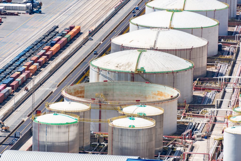
Engineering Services for Reliable Industrial Projects Industrial projects depend on more than drawings and calculations. Successful execution requires practical planning, code compliance, coordination between disciplines, and engineering decisions that support long term reliability. That is where professional Engineering Services play an important role. From piping systems and pressure equipment to structural analysis and design registration support, engineering services help manufacturers, plant owners, and EPC companies move projects forward with confidence. For companies operating in Canada, the USA, and international markets, working with an experienced engineering partner can improve project efficiency while helping meet applicable regulatory and operational requirements. What Are Engineering Services? Engineering Services refer to technical and professional support provided throughout the lifecycle of an industrial project. These services may include: Mechanical and piping design Piping stress analysis Structural engineering support Pressure vessel calculations CRN registration assistance Professional Engineer review and stamping Drafting and 3D modeling Code compliance assessments The exact scope depends on the industry, project size, and jurisdictional requirements. Why Engineering Services Matter Improving Safety and Reliability Industrial systems often operate under high pressure, elevated temperatures, or demanding environmental conditions. Proper engineering review helps identify design risks before fabrication or installation begins. For example, piping stress analysis can help prevent excessive nozzle loads, vibration issues, or thermal expansion problems that could affect equipment performance. Supporting Regulatory Compliance Projects across Canada and the USA are frequently subject to industry codes, standards, and provincial or state regulations. In Canada, pressure equipment projects may also require CRN registration depending on the application. Requirements can vary by province and local authority, so it is important to confirm the specific obligations for each project location. Reducing Delays and Rework Engineering coordination early in the project can reduce fabrication changes, installation conflicts, and approval delays later in the process. Clear calculations, accurate drawings, and organized documentation often help projects move more efficiently through procurement and regulatory review. Common Engineering Services Used in Industrial Projects Piping Design and Stress Analysis Piping systems must safely manage pressure, temperature, and operational loads. Engineering reviews help ensure systems remain flexible, properly supported, and compliant with applicable codes. This is especially important for steam systems, process piping, and critical equipment connections. CRN Registration Support Many pressure-retaining items used in Canada require Canadian Registration Number approval before installation. Engineering support may include: Design calculations Drawing preparation Code compliance review Submission coordination with provincial regulators For international manufacturers, understanding Canadian registration requirements can be particularly important when entering the market. Professional Engineer Review Certain projects require review or authentication by a licensed Professional Engineer depending on local regulations and project scope. Professional engineering oversight helps confirm that designs align with applicable standards and engineering practices. Structural and Equipment Support Design Industrial facilities rely on properly designed supports for piping, vessels, skids, and related systems. Structural analysis helps verify that supports can safely manage operational and environmental loads. Engineering Services in Canada and the USA Engineering requirements can differ significantly between jurisdictions. Canadian projects may involve provincial regulators, CRN requirements, and Professional Engineer licensing obligations. In the USA, project requirements may vary by state, client specification, and industry sector. Because regulations and approval pathways differ, companies benefit from engineering teams familiar with both technical standards and practical project execution. How MECS Supports Industrial Clients MECS provides professional Engineering Services for industrial projects across Canada, the USA, and international markets. Our services include: Piping and mechanical design Piping stress analysis CRN support and design registration Pressure equipment engineering Structural engineering support Professional Engineer stamping where required Drafting and technical documentation MECS works with manufacturers, fabricators, EPC firms, and plant owners across multiple industries, helping clients address both technical and regulatory challenges. Choosing the Right Engineering Partner Selecting an engineering consultant is not only about technical software capability. Practical industry knowledge, communication, and understanding of real project constraints are equally important. A strong engineering partner should provide: Clear technical documentation Practical recommendations Responsive communication Familiarity with relevant codes and standards Support through design and approval stages This helps projects stay aligned with schedule, safety, and operational goals. Conclusion Professional Engineering Services help industrial projects operate safely, efficiently, and in compliance with applicable regulations. From piping stress analysis and structural support design to CRN registration assistance, the right engineering support can reduce risk and improve project outcomes. MECS provides practical engineering solutions tailored to industrial clients in Canada, the USA, and worldwide. Contact our team to discuss how we can support your next project.
FEA in Pressure Vessel Design: Moving Beyond Design by Rule
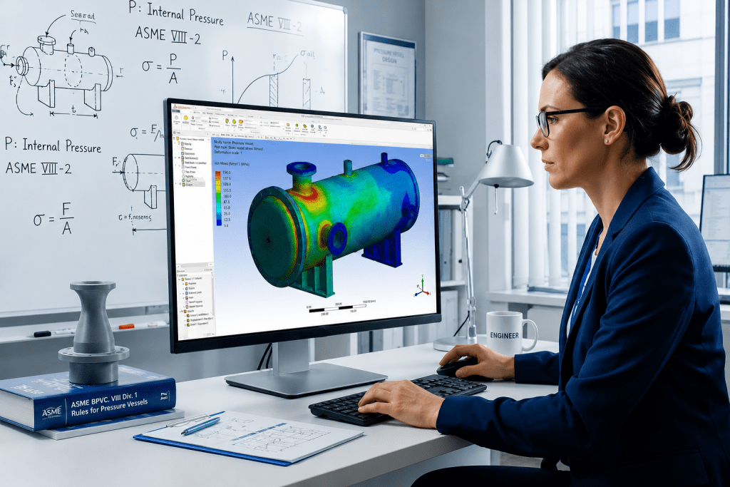
FEA in Pressure Vessel Design: Moving Beyond Design by Rule The global standard method for pressure vessel design has been the “Design-by-Rule” (DBR) methodology governed by popular Boiler and Pressure Vessel Codes like ASME Section VIII, Division 1, AD 2000, PD 5500, EN13445 among others. Design by Rule (DBR) relies on established formulas and safety margins to size components like cylinders, heads, and nozzles. However, these rules only work if you assume the equipment is symmetrical and the loads are simple enough to be conservatively analysed by formula-based methods. The equipment takes physical shape to meet these process demands, the resulting geometry often outgrows the simple mold of established rules in the Code. A vessel’s initial sizing is driven by the process engineer (They dictate exactly what the system needs to function). When a design falls outside the validated scope of standard rules, every major global code provides an “Alternative Design” provision, most famously recognized as ASME Section VIII Division 1’s Paragraph U-2(g) but equally embedded in the core principles of EN 13445, PD 5500, and AD 2000. As, the Code invokes Alternate analysis requirement clause. This clause essentially says if the book doesn’t cover your geometry, you should mathematically prove the design is safe. Alternative Design Provisions (ASME U-2(g), EN 13445, PD 5500, AD 2000) It is a common misconception that triggering these clauses mandates an immediate jump to Finite Element Analysis (FEA). These are Alternative Analysis provisions. They dictate that when the standard rulebook is silent, the engineer is to validate the structural integrity using recognized engineering mechanics. This can be achieved through closed-form analytical calculations (first principles), proof testing, the application of complementary international standards, OR when the geometric complexity outpaces manual mathematics advanced numerical methods like FEA. Let’s Explore what are some potential cases Designers and Engineers can come across which will require them to search beyond DBR methods laid out in the respective Code. In day-to-day static and fixed equipment design, we frequently run into scenarios where standard code rules just aren’t enough. Here are a few of the most common, real-world design issues where FEA becomes an absolute necessity. While the terminology in the examples below leans on ASME Section VIII, Division 1, the underlying physics applies across the board. Because every major “Design by Rule” standard (from EN 13445 to PD 5500) relies on the same basic assumptions of symmetry and uniform loading, they all share the exact same blind spots. Common Real-World Design Scenarios Requiring FEA Local Load Analysis of Geometries Outgrowing WRC LimitsWe use WRC 537 / 107 for analysing static reactions on pressure boundaries, some of the following examples are: Nozzle piping loads on shell and shell to nozzle junction lifting lug and tailing lug attachment to shell. Platform clips and pipe support clips to shell Support legs, Support bracket to shell Nozzle to shell / head junction is overstressed We all rely on WRC 107 / 537 and sometimes WRC 297 to determine local stresses in the shell at structural discontinuities such as legs, support lugs and clip attachments. This bulletin does not address rectangular attachments to shells of double-curvature, and these charts have strict geometric limits. If your nozzle is massive compared to the vessel, or if the shell is extremely thin, or if any rectangular attachment like lug, clips, etc., are welded on double curvature components like heads. WRC methods simply do not provide methods to analyse the concerned geometry. In highly loaded junctions such as a central nozzle supporting an agitator assembly. The standard software with WRC 107 / 537 will provide overstress results and cannot calculate the structural stiffeners. To properly analyze this pressure boundary and guarantee the design is safe, a 3D FEA model is the only practical solution. Non-Uniform Tubesheets Standard TEMA and ASME rules for sizing tubesheets rely on one massive assumption: that the plate is uniformly drilled with holes. For tube layouts which are not uniform where tubesheet is perforated for a small region and large part of it is an untubed area, but real-world heat exchangers often require multi-pass flow, which means there is un-tubed metal. These solid strips act like rigid steel beams. When pressure hits the tubesheet, it doesn’t bend evenly; the un-tubed lanes stay stiff while the drilled areas bow outward. Standard formulas cannot calculate this uneven bending, leading to unexpected shear forces that can rip the tube-to-tubesheet welds apart. As analysts, we model the exact, true geometry of the tubesheet, including every solid un-tubed lane and irregular perimeter gap. This allows the simulation to capture the exact bending behavior and locate the high localized stresses where the flexible tubed region meets the rigid un-tubed metal, ensuring the welds will hold under operating pressure. Large Openings, Extreme Aspect Ratios, and Knuckle Nozzles When you introduce unconventional geometries—like massive openings, obround cutouts, offset/tilted nozzles, or nozzles located right on a head knuckle. Per ASME UG-36(a)(1), if the aspect ratio (the long chord divided by the short chord of the opening) exceeds 2.0, the code warns that additional reinforcement is needed to resist complex bending forces. However, ASME provides no elementary formula for how much reinforcement is needed. Because of this, software will simply flag a permanent warning. This warning will never “disappear” just by artificially thickening the repad in the software, because the error is tied to the physical dimensions of the hole, not the thickness of the steel. The Large Nozzle Limit: If the nozzle is massive, Appendix 1-7(b) takes over. But even those advanced rules have a ceiling. If the ratio of the nozzle radius to the vessel radius exceeds 0.7, the software will complete the Appendix 1-7 analysis but immediately flag that the geometry is still too extreme, requiring additional analysis per U-2(g). Fatigue Life and Cyclic loading Pressure vessels aren’t always static. If a vessel undergoes thousands of pressure or temperature cycles over its lifetime (like a batch reactor continuously filling and draining), the metal can eventually crack from fatigue even if
Analyzing Seismic Loads in Piping Systems for Earthquake-Prone Areas
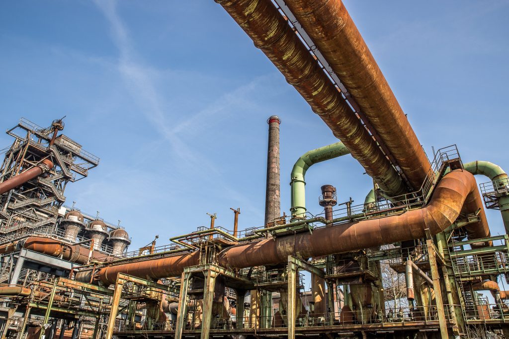
Analyzing Seismic Loads in Piping Systems for Earthquake-Prone Areas Home / Learning In earthquake-prone regions, designing resilient piping systems is essential to ensure public safety and protect infrastructure. Seismic loads introduce unique challenges, including dynamic forces from ground movement and structural interactions between pipelines and their surroundings. A well-engineered piping system must withstand seismic stresses, maintaining functionality during and after seismic events. This article delves into the critical aspects of seismic design for piping systems, covering the methodologies, analytical techniques, and practical benefits of incorporating seismic resilience into pipeline engineering. Why Seismic Design Matters in Piping Systems Piping systems in earthquake-prone regions are vulnerable to damage due to seismic forces. The impact ranges from minor deformation to catastrophic failure, leading to hazardous leaks, equipment damage, and operational shutdowns. This risk is particularly high in safety-critical industries such as nuclear power, chemical processing, and oil and gas.To mitigate these risks, engineers use specialized seismic analysis and design methodologies to predict and accommodate the effects of ground movements. These designs factor in: Seismic hazards specific to the region. Piping system geometry and material properties. Interaction with supporting structures. Key Factors in Seismic Design Seismic analysis is influenced by several critical factors, including the natural frequencies, restraint configuration, and response spectra. Here’s an in-depth look: Piping Geometry and Restraint ConfigurationThe natural frequency of a piping system is dictated by its geometry and restraint layout. By strategically altering these elements, engineers can “tune” the system to avoid resonance and reduce seismic loads. Response SpectraResponse spectra measure how a structure, such as a building or support, amplifies ground vibrations during an earthquake. Understanding this amplification is critical for assessing the piping system’s response and designing appropriate mitigation measures. Earthquake History and Regional SeismicitySeismic design starts with an assessment of earthquake potential, based on historical seismic data. This includes analyzing previous earthquakes’ intensity, frequency, and impact, combined with geological and geotechnical studies. Methods for Seismic Analysis and Design Seismic analysis employs both static and dynamic methods, each suited to specific scenarios. The five primary techniques are: Uniform Building Code (UBC) Analysis: The UBC provides a framework for estimating seismic loads based on regional damage potential. Earthquake zones are classified as 0 (minimal risk) to 3 (high risk), and seismic coefficients (Z) are assigned accordingly. The design load is calculated using the formula: g=ZKCT Where: g = static equivalent g-factor to use for seismic design, multiples of gravity Z = seismic coefficient based on earthquake zone, equal to 0.0 for Zone 0,0.25 or Zone 1, 0.5 for Zone 2, and 1.0 for Zone 3 K = structure type constant, ranging from 0.67 to 3.0, dimensionless C = 0.05/T^(1/3), but not greater than 0.1 T = fundamental period (inverse of frequency) of structure, sec This method converts dynamic seismic forces into an equivalent static load, simplifying analysis for routine design applications. Nuclear Seismic Design: Nuclear facilities require stringent seismic designs due to the critical nature of their operations. This involves advanced modeling techniques and adherence to strict regulatory codes. The piping in these facilities undergoes comprehensive stress evaluations, ensuring it meets allowable limits even during extreme seismic events. Time History Analysis: Time history analysis uses earthquake records to simulate seismic effects on piping systems. This method involves: Plotting ground motion data (displacement, velocity, acceleration) over time for three spatial directions. Applying these data to a dynamic model of the piping system. The analysis provides detailed insights into stress, displacement, and support loads at each time step during an earthquake. Although highly accurate, this method is computationally intensive and expensive, making it ideal for critical systems in high-risk regions. Modal Analysis Using Response Spectra: Modal analysis simplifies dynamic analysis by breaking a piping system into individual vibration modes. Engineers calculate the response of each mode to seismic input and combine these to determine the total system response. Key equations include: Where, This method is cost-effective compared to time history analysis and widely used for complex piping systems. When the applied acceleration is removed from an undamped oscillator (a=0,C=0), the system continues to vibrate at its undamped natural frequency (ωnomega_nωn). This frequency is critical in assessing the dynamic response of the piping system. Applying a vibratory motion to the system can result in higher accelerations on the mass than those input at the base. This outcome depends on the interaction of velocity and displacement at specific moments during the seismic event. By examining the amplification factor, the shape of the response spectra becomes clear: Flexible Range: When the oscillator’s natural frequency is much smaller than the forcing frequency, the amplification factor approaches zero. Resonant Range: As the oscillator frequency nears the forcing frequency, the amplification factor increases significantly, resulting in two distinct peaks. Rigid Range: When the oscillator frequency is much greater than the forcing frequency, the amplification factor approaches 1.0. The acceleration matches the imposed motions, termed as zero-period acceleration. These ranges dictate the dynamic behavior of the system and highlight how seismic forces amplify or attenuate depending on frequency relationships. The total seismic response of the piping system is determined by summing the responses of its individual vibration modes. These responses depend on the natural frequencies of the system, which are influenced by its geometry and restraint configuration. By adjusting these parameters, engineers can “tune” the system to modify its natural frequencies, thereby reducing its seismic response and associated stresses. The response spectra effectively represent the interaction between the building and the piping system during an earthquake. Natural frequencies and mode shapes of the piping system are typically calculated using a lumped-mass model in computational analysis, which employs an eigenvalue-eigenvector algorithm. Static Analysis: Static analysis is employed when detailed dynamic modeling is unnecessary. It approximates seismic forces using a simplified approach. For example: Using response spectra data, engineers identify the acceleration corresponding to the system’s fundamental frequency. Multiplying this acceleration by the piping’s linear weight determines the static seismic load. This conservative method is suitable for less critical applications or systems where response spectra data
Understanding Third-Party Verification: Why It’s Essential in Engineering Projects

Understanding Third-Party Verification: Why It’s Essential in Engineering Projects Home / Learning With the engineering projects becoming more complex, third-party verification has emerged as a cornerstone for ensuring quality, regulatory adherence, and reliability. This independent assessment is essential for enhancing project integrity and transparency, where objectivity is important to meeting high standards. It covers a spectrum of critical activities—such as inspections, document reviews, and quality audits—that verify each project component meets precise industry benchmarks. Here, we explore the importance of third-party verification, its detailed processes, and the substantial benefits it brings to engineering projects. What is Third-Party Verification? Third-party verification is a process in which an independent party assesses various project facets—such as design specifications, material properties, regulatory compliance, constructability, operability, maintainability, and safety (COMS) aspects – to ensure adherence to industry standards. The neutrality of third-party verifiers eliminates potential conflicts of interest ensuring a fair and unbiased evaluation. MECS Engineering offers expert third-party verification services across industries such as Process, Power (Nuclear and Fossil), Co-Generation, Oil and Gas, Refineries, Chemical and Petrochemical, and Pharmaceutical Facilities. Key Activities in Third-Party Inspection at MECS Engineering: Third-party verification at MECS Engineering typically involves the following activities: Documentation Review: Ensuring design documents and specifications meet project and industry standards. Code Compliance Verification: Confirming adherence to codes such as ASME for engineering and safety standards. Regulatory Compliance: Verifying that designs align with applicable regulations to ensure project viability. Safety and Operability Assessment: Reviewing designs for safety and operational effectiveness. Comprehensive Reporting: Providing a detailed report with compliance findings and recommendations. Why Third-Party Verification Matters Objective Evaluation: Our independent verification ensures unbiased evaluation, free from internal project pressures. This impartiality is especially important for assessing components where project teams may have vested interests, such as financial targets or project deadlines. Compliance Assurance: Engineering projects must comply with various standards and codes. Our team at MECS Engineering possess in-depth regulatory knowledge, providing a rigorous assessment to ensure that your projects are fully compliant with local and international regulatory requirements, Risk Mitigation: Early identification of potential issues is crucial for managing risk. By detecting discrepancies and recommending improvements, our team helps in addressing risks proactively, contributing to seamless project execution. Technical Proficiency: Our team of experts, ensures that your project components are assessed by professionals knowledgeable industry leader in specific technical areas, thereby upholding project standards. In conclusion, third-party verification might sometimes appear as an extra step, but it’s essential for ensuring project quality, compliance, and long-term reliability. By providing an objective evaluation, MECS Engineering safeguards projects against oversights and elevates them to meet stringent industry standards. This independent verification reinforces project success, builds trust, and minimizes risks that could compromise quality or lead to costly rework. To discuss how MECS Engineering can add value to your projects through third-party verification, contact us at www.mecsengineering.com
Importance of Optimal Piping Layout for Efficient Stress Analysis in High-Temperature Lines
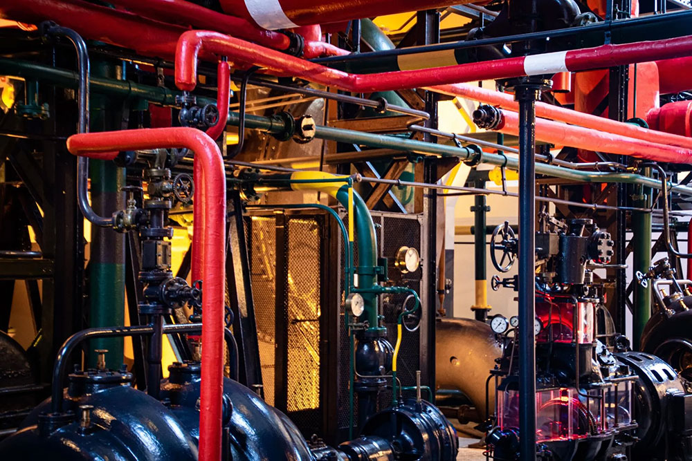
Importance of Optimal Piping Layout for Efficient Stress Analysis in High-Temperature Lines Home / Learning In industries such as oil and gas, chemical processing, and power generation, high-temperature piping systems play a crucial role in ensuring the safe and efficient transportation of fluids. However, designing these systems requires meticulous attention to thermal expansion, stress analysis, and layout considerations. A poorly designed piping layout can lead to serious issues such as excessive stresses, mechanical failures, and even system shutdowns. The optimal piping layout, especially in high-temperature lines, is essential for reducing stress, prolonging equipment life, and ensuring operational safety. Challenges of High-Temperature Piping Systems High-temperature environments introduce an additional layer of complexity to piping systems. In such conditions, metal pipes expand when exposed to heat, which, if not accounted for, can lead to significant stress-related problems like pipe rupture, material fatigue, misalignment of connected equipment and Catastrophic failures. This is where thermal expansion becomes critical. Without accounting for the temperature variations and resulting stresses, the piping system could face catastrophic failures. A well-designed piping layout is essential to managing these stresses and ensuring long-term operational stability. Stress Analysis in Piping Systems Stress analysis is the process of evaluating how various forces act on a piping system, particularly under conditions of high temperature, pressure, and external loads. In high-temperature systems, the primary source of stress is thermal expansion. When thermal expansion is restrained by supports, anchors, or adjacent equipment, it creates internal forces, leading to thermal stress. Thermal Expansion and Its Impact on Piping Systems In high-temperature systems, one of the most critical factors affecting the design and operation of the piping system is thermal expansion. As temperature increases, materials expand—a natural physical phenomenon. Conversely, in cryogenic services, materials contract as temperature decreases. This expansion or contraction can induce significant mechanical stress, especially in long pipe runs, if not adequately accounted for in the layout. Formula for Linear Thermal Expansion: The formula that describes this expansion is as follows: Δx=α×L×ΔT Where: Δx is the change in length (expansion or contraction) α is the thermal coefficient of linear expansion (a material-specific property), L is the original length of the pipe, ΔT is the change in temperature. Even small temperature increases can cause significant expansion over long piping runs, creating stress at joints, supports, and equipment connections. Therefore, understanding and managing thermal expansion is crucial to preventing excessive stress in the system. Thermal Expansion and Piping Layout The poorly planned layouts can magnify the effects of thermal expansion. For instance, a straight run of pipe with minimal support or anchorage may be more prone to thermal stresses, leading to issues such as: Cracking in the pipe material or welds, Leaks at joints due to excessive movement, Bowing or sagging in unsupported pipe sections, Damage to surrounding support structures and misalignment of equipment. How Optimal Piping Layout Reduces Stress in High-Temperature Lines Designing an effective piping layout in high-temperature applications can drastically reduce stress within the system. Here are key layout considerations for mitigating thermal expansion-related stress: Strategic Placement of Supports and Anchors: Supports and anchors serve as the backbone of a piping system, controlling movement and maintaining alignment. However, improper placement can lead to localized stress concentration. A carefully planned layout ensures: Supports: Positioned to allow pipes to expand and contract freely, avoiding sagging or bowing. Fixed supports should be limited to prevent thermal stress accumulation. Anchors: These should be placed where pipes must be restrained, yet positioned to limit stress transfer to sensitive equipment such as turbines or pumps. By using flexible guides, lateral movement can be accommodated while constraining vertical displacement, reducing stress at key points. Use of Expansion Loops : Expansion loops are critical in absorbing thermal expansion without transferring stress to the entire system. By incorporating loops or offsets in the piping layout, the pipe is free to expand and contract naturally, reducing stress concentrations. Expansion loops come in two main configurations: Horizontal Expansion Loops: These are common in long, straight piping runs, providing flexibility that reduces the risk of buckling or deformation. Vertical Loops: Effective in systems with vertical piping runs, although care must be taken to avoid drainage issues or vapor pockets. Rerouting the Pipe: Straight runs of piping are particularly prone to high thermal stresses since expansion occurs in one direction. Introducing bends and elbows into the piping layout allows expansion to be distributed more evenly across the system, reducing stress on any single component. This rerouting process makes the system inherently more flexible and better able to absorb thermal movements. Incorporating Flexible Components: In high-temperature systems, flexible components like bellows, sliding supports, and expansion joints are essential. These components absorb axial movement caused by thermal expansion, allowing the piping to move without inducing stress. However, they require precise design and maintenance to ensure they can withstand operational conditions like temperature, pressure, and flow. Key Factors in Stress Analysis for Piping Layout While optimizing the piping layout, detailed stress analysis is critical to evaluate the design’s adequacy under operational conditions. Key factors in this analysis include: Temperature Differential (ΔT): A large ΔT results in significant thermal expansion, and the system must be designed to accommodate these movements. Material Selection: Different materials have varying thermal expansion coefficients. Selecting materials suitable for the system’s operating temperature is crucial. Code Compliance: Following ASME guidelines ensures the system meets safety standards. Simplified formulas can indicate whether detailed stress analysis, using tools like CAESAR II®, is necessary. Branching and Complex Layouts: Piping systems with multiple branches or varied pipe sizes require individual evaluation of each section to ensure they can withstand thermal stresses. Benefits of an Optimized Piping Layout in Stress Analysis The piping layout directly supports stress analysis by reducing the likelihood of excessive stress buildup and improving system reliability. Here’s how: Minimizes Excessive Stress: A well-designed layout with flexible loops like C or S shapes prevents excessive strain caused by expansion and contraction. Stress analysis using tools like
Piping Engineering: Design, Analysis, and Compliance
Piping Engineering: Design, Analysis, and Compliance Home / Learning Piping systems, are integral to numerous industrial processes, used to transport fluids between different locations. These systems are composed of various components, including pipes, fittings, and valves, all assembled and designed to ensure efficient and safe fluid transport. Piping engineering is the discipline that integrates material and mechanical engineering principles with specialized techniques like stress analysis and piping layout design. This comprehensive approach converts process documents, such as Piping & Instrumentation Diagrams (P&IDs) and Process Flow Diagrams (PFDs), into detailed piping drawings and data, which guide the procurement, assembly, and testing of piping systems. The Crucial Role of Piping Design The design phase of piping engineering is critical, involving the creation of plot plans, equipment layouts, and three-dimensional (3D) models that define the physical layout of the piping system. Plot Plan Development: It is a top-level drawing showing the entire facility, including equipment, buildings, and structures. It is important to ensure that site constraints, safety, and operational efficiency are considered. Proper spacing between hazardous areas, clear access routes for maintenance and emergencies, and optimal equipment positioning are key factors that contribute to reducing pipeline lengths and enhancing workflow. Equipment Layout: Detailing the position of equipment like pumps, compressors, and tanks within the plot plan is essential. Engineers ensure adequate spacing for maintenance, proper alignment to optimize fluid flow, and the inclusion of support structures for stability and accessibility. 3D Modeling Software: Advanced software tools like AutoCAD Plant 3D and PDMS allow engineers to create virtual representations of piping systems. These 3D models enable the visualization of the entire network, identification of potential clashes, and simulation of fluid flow dynamics, leading to accurate and efficient design. From these models, detailed isometric drawings and material take-offs can be generated. Piping Route and Support Design: The design of efficient piping routes minimizes pressure drops and meets process requirements. Proper support and anchoring systems are critical for managing thermal expansion, vibration, and weight, preventing sagging and stress on connections. Piping Stress Analysis to Prevent Operational Failure Piping stress analysis is a vital process that ensures the safety, reliability, and efficiency of piping systems. The analysis is the study of stresses in a piping system. It is a term applied to calculations, which addresses the static and dynamic loads such as dead weight (self-weight of the pipe including fluid, fittings and its associated components), internal and external pressure, thermal loads (due to change in temperature), seismic loads, wind loads, vibration, water hammer, stream hammer, slug force, PSV reaction force, etc. to produce a comprehensive analysis report. This process is essential to ensure that piping systems can withstand various loads during operation without compromising their structural integrity. Types of Loads in Piping Systems Piping systems are subject to several types of loads, each contributing to the overall stress experienced by the pipes: Ensuring Structural Integrity: Stress analysis evaluates the effects of thermal expansion, contraction, and other loadings on the piping system. By understanding the stress distribution and potential failure points, engineers can design piping systems that maintain structural integrity under extreme conditions. Preventing Overstress: High-temperature environments can lead to overstress in piping components, supports, and connected equipment. Stress analysis helps in optimizing the design to prevent overstress and reduce the likelihood of failures, such as cracking or rupture. Compliance with Codes and Standards: Piping systems must comply with various industry codes and standards, which specify allowable stress values, material requirements, and design considerations. Stress analysis ensures that the piping system meets these requirements, particularly in high-temperature applications where allowable stress values are reduced. Optimizing Design: While ensuring safety is paramount, overdesign can lead to unnecessary costs and inefficiencies. Stress analysis allows for the optimization of piping systems by accurately predicting stress levels and enabling the use of appropriate materials and supports without excessive safety factors. Conducting Piping Stress Analysis Piping stress analysis involves creating a detailed model of the piping system and simulating the various loads it will encounter during operation using specialized software tools. Specialized Software Tools: Engineers use software like CAESAR II, AutoPIPE, ROHR2, and PIPESTRESS to perform both static and dynamic stress analysis, model piping systems, and analyze flexibility and stress under different loads. Modeling the Piping System: The initial step involves developing a detailed model that includes all relevant components—pipes, fittings, valves, supports, and equipment connections. Key aspects are as follows:: Geometry: Accurate representation of the piping layout, including lengths, diameters, and routing. Material Properties: Incorporating the mechanical properties of the piping materials, such as Young’s modulus, Poisson’s ratio, thermal expansion coefficients, and yield strength. Boundary Conditions: Defining the constraints and supports, such as fixed supports, sliding supports, and anchors. Simulating Loads: Engineers simulate various loads, including internal pressure, thermal expansion, weight loads, external forces, and dynamic loads, to assess how the piping system will respond during operation. Internal Pressure: Simulations assess hoop, longitudinal, and radial stresses to ensure the pipe can withstand internal fluid pressure without failure. Thermal Expansion: Temperature changes cause pipes to expand or contract, with simulations helping to design expansion joints and supports that prevent stress-related issues Weight Loads: Engineers simulate the combined weight of the pipe, fluid, and insulation to ensure the support system prevents sagging or overstressing. External Forces: Simulations consider wind, seismic activity, and soil pressure to design supports and bracing that protect the system from external environmental stresses. Dynamic Loads: Transient conditions like water hammer or pump startup/shutdown are simulated to assess the system’s ability to handle sudden changes in flow or pressure. Assessing the System’s Response: The system’s response to loads is evaluated by checking for excessive deformation, comparing stress levels to code limits, and conducting fatigue analysis to identify potential failure from cyclic loading. Identifying and Mitigating Issues: If analysis reveals issues like overstress or excessive deformation, engineers take corrective actions as followed:4 Re-routing Piping: Modifying the layout to reduce stress concentrations and improve flexibility. Adding Supports: Introducing additional supports or changing the type of supports to better manage the loads. Using Expansion Joints: Incorporating expansion joints or loops to
Advanced Piping Stress Analysis for High-Temperature Services
Advanced Piping Stress Analysis for High-Temperature Services </h1 > Home / Learning When piping systems are exposed to high temperatures, the physical and mechanical properties of the piping materials undergo significant changes, leading to complex challenges in maintaining system integrity and safety. This article delves into the effects of high temperatures on piping systems, the importance of stress analysis in such environments, and the techniques and tools used to perform these analyses effectively. The Impact of High Temperature on Piping System High-temperature environments have a profound impact on the behavior of piping designs. As the temperature rises, the piping material expands, leading to displacement in the system. This displacement is not uniform; instead, it can cause the piping to move vertically, axially, and laterally. The extent of these movements increases with temperature, creating additional stresses and strains within the system. Thermal Expansion and Contraction: The primary effect of temperature changes on piping systems is thermal expansion and contraction. When the temperature increases, the piping material expands, leading to thermal stresses. Conversely, when the temperature decreases, the material contracts, which can also induce stress. These thermal movements result in significant loads on supports, anchors, and connected equipment nozzles, potentially leading to system failure if not properly managed. Creep and Reduced Allowable Stress: At temperatures above a material’s creep threshold (typically one-third of its melting temperature), creep deformation begins. Creep is the slow, permanent deformation of a material under constant stress, exacerbated at high temperatures. Additionally, the allowable stress values of materials decrease with rising temperatures, making the system more susceptible to failure. This reduction in allowable stress values necessitates careful consideration during design and stress analysis to ensure the piping system’s safety and reliability. Corrosion and Material Degradation: High temperatures can accelerate corrosion mechanisms and increase the rate of corrosion in piping systems. Additionally, specific materials may experience embrittlement or degradation at elevated temperatures, further compromising system integrity. The selection of corrosion-resistant materials and appropriate insulation is crucial for high-temperature piping systems. Thermal Bowing and Shakedown: During plant start-up, two-phase flow in long pipes exposed to high temperatures can lead to thermal bowing, where the pipe bends due to uneven heating. At very high temperatures, piping may operate in a creep range, leading to permanent yielding of the material. When the system cools down during shutdowns, the piping may not return to its original position, a phenomenon known as thermal shakedown. The Importance of Stress Analysis in High-Temperature Piping Systems Given the complexities introduced by high temperatures, stress analysis becomes an essential procedure for ensuring the safety and reliability of piping systems. Piping stress analysis helps identify areas with high relative risk, enabling engineers to manage these areas effectively and mitigate the likelihood of failures. The primary objectives of stress analysis in high-temperature services are: Ensuring Structural Integrity: Stress analysis evaluates the effects of thermal expansion, contraction, and other loadings on the piping system. By understanding the stress distribution and potential failure points, engineers can design piping systems that maintain structural integrity under extreme conditions. Preventing Overstress: High-temperature environments can lead to overstress in piping components, supports, and connected equipment. Stress analysis helps in optimizing the design to prevent overstress and reduce the likelihood of failures, such as cracking or rupture. Compliance with Codes and Standards: Piping systems must comply with various industry codes and standards, which specify allowable stress values, material requirements, and design considerations. Stress analysis ensures that the piping system meets these requirements, particularly in high-temperature applications where allowable stress values are reduced. Optimizing Design: While ensuring safety is paramount, overdesign can lead to unnecessary costs and inefficiencies. Stress analysis allows for the optimization of piping systems by accurately predicting stress levels and enabling the use of appropriate materials and supports without excessive safety factors. Piping Stress Analysis Performing stress analysis on high-temperature piping systems requires a combination of advanced techniques and tools. These methods help engineers evaluate the complex interactions between temperature, pressure, and mechanical loads, ensuring that the piping system operates safely and efficiently. Finite Element Analysis (FEA): FEA is a powerful computational tool used to simulate and analyze the stress distribution in piping systems. By creating a detailed model of the piping system, engineers can simulate various operating conditions, including temperature changes, pressure fluctuations, and mechanical loads. FEA helps in identifying high-stress areas and optimizing the design to prevent failures. Thermal Stress Analysis: This specialized analysis focuses on the thermal effects on piping systems. It considers the full thermal stress range, from minimum to maximum operating temperatures, and evaluates the impact of temperature gradients on the system. Thermal stress analysis is particularly important for piping systems exposed to extreme temperature variations, as it helps in designing appropriate expansion joints, supports, and other components. Creep Analysis: For piping systems operating at high temperatures, creep analysis is essential to evaluate the long-term effects of sustained high temperatures on material deformation. Creep analysis helps in predicting the service life of the piping system and identifying the need for periodic inspections or maintenance. Support and Anchor Design: The design of supports and anchors is critical in high-temperature piping systems. Engineers must consider the thermal expansion and contraction of the piping, as well as the additional loads imposed by temperature changes. Specialized supports, such as spring hangers, snubbers, and anti-friction slide plates, are often required to accommodate thermal movements and prevent overstress. Material Selection: The choice of materials for high-temperature piping systems is crucial. Materials must be able to withstand high temperatures without significant degradation, and they should have appropriate mechanical properties, such as high creep resistance and corrosion resistance. In some cases, exotic alloys or composite materials may be required to meet these demands. Insulation and Expansion Joints: Insulation is vital for maintaining the temperature within the piping system and protecting personnel from hot surfaces. In high-temperature applications, the insulation thickness is increased, and materials like ceramic wool are used instead of conventional insulation materials. Expansion joints, while expensive and challenging to maintain, are often necessary to accommodate
CRN Registration Vs ASME Certification: Key Differences Explained
CRN Registration Vs ASME Certification: Key Differences Explained Home / Learning ASME Certification and CRN registration are both essential for pressure equipment compliance, but they serve distinct purposes. While ASME Certification is a globally recognized standard for safety and quality, CRN registration is a legal requirement specific to Canada. Together, they ensure that pressure equipment meets stringent regulatory and operational standards. In industries reliant on pressure-containing equipment, such as power generation, oil and gas, and chemical processing, adherence to safety, quality, and reliability standards is essential. In Canada, compliance is ensured through two key certifications: ASME (American Society of Mechanical Engineers) Certification and CRN (Canadian Registration Number) Registration. Both are vital but address different aspects of pressure equipment safety in the Canadian regulatory environment. ASME Certification: An International Benchmark ASME certification is recognized worldwide as a benchmark for pressure equipment, including pressure vessels and piping systems. It ensures that the equipment has been designed, manufactured, and tested in accordance with the stringent standards set by ASME. These standards cover aspects such as design, materials, construction, and inspection procedures, making ASME certification a symbol of quality and safety. ASME certification is particularly crucial in industries where the failure of pressure equipment could lead to catastrophic consequences. However, while ASME certification is essential, it is not sufficient for the legal use of pressure equipment in Canada. This is where CRN registration comes into play CRN Registration: Ensuring Jurisdictional Compliance in Canada The Canadian Registration Number (CRN) is a unique identifier issued by regulatory bodies in Canadian provinces and territories. It signifies that the pressure equipment opearting above 15 psig meets local safety regulations and is suitable for operation under Canadian conditions. Despite having ASME certification, equipment must obtain a CRN before it can be legally used in Canada. Owners, users, agents, manufacturers and contractors of boilers or pressurized equipment must register equipment designs to ensure the equipment meets safety standards. Before pressurized equipment can be used, its design must undergo an engineering review to ensure it complies with the CSA B51 standard and additional/ exempted rules of province it will be used in to obtain CRN. Differences Between ASME Certification and CRN Registration in Canada Jurisdictional Compliance ASME Certification: Confirms that the equipment adheres to internationally recognized standards. However, ASME standards are general and do not account for the specific regulatory requirements of individual Canadian provinces and territories. CRN: Ensures compliance with local regulations enforced by provincial or territorial authorities, such as the Technical Standards and Safety Authority (TSSA) in Ontario or ABSA in Alberta. These bodies evaluate the equipment to ensure it meets the specific safety and operational standards required in their jurisdictions. Local Standards and Modifications ASME Standards: Provide a universal set of criteria for the design and construction of pressure equipment, widely accepted across various industries and regions. Provincial/Territorial Requirements: Canadian jurisdictions may impose additional requirements, tailored to local conditions. For example, equipment may need to be modified to withstand extreme cold climates or incorporate specific safety features. The CRN process ensures that these local modifications are reviewed and approved before the equipment can be used. Legal Requirement Mandatory CRN: In Canada, obtaining a CRN is a legal requirement for all pressure equipment, including pressure vessels and piping systems. Each piece of equipment must have a valid CRN for every province or territory in which it will operate. Without a CRN, the equipment cannot be legally installed or operated, regardless of its ASME certification. Inspection and Approval ASME Inspection: Involves rigorous inspections, testing, and audits to ensure that the equipment meets ASME standards. CRN Review: Adds another layer of scrutiny, with local regulatory authorities conducting design verification, material assessments, and ensuring compliance with Canadian safety codes and standards. Interrelationship Between ASME Certification and CRN Registration ASME certification often serves as a foundation for CRN registration. In many cases, equipment must first obtain ASME certification before it can be considered for CRN approval. The CRN process then involves an additional review to ensure the equipment complies with the specific regulations and environmental conditions in Canada. This dual requirement underscores the importance of both certifications in maintaining the highest safety and quality standards for pressure equipment. At MECS Engineering, we simplify the CRN registration process, ensuring your pressure equipment complies with Canadian regulations. Our team handles everything from design verification to documentation, streamlining approval for timely compliance. Trust us to guide you through the complexities of CRN for your piping systems, pressure vessels, and more. Contact us today for expert guidance and smooth approval across Canada. For more information about CRN process in Canada read at: Province/Territory Regulatory Authority Website Alberta ABSA (Alberta Boilers Safety Association) www.absa.ca British Columbia Technical Safety BC www.technicalsafetybc.ca Manitoba Office of the Fire Commissioner (OFC) www.firecomm.gov.mb.ca New Brunswick ACI Central Inc. www.acicrn.com Newfoundland & Labrador ACI Central Inc. www.acicrn.com Northwest Territories ACI Central Inc. www.acicrn.com Nova Scotia ACI Central Inc. www.acicrn.com Nunavut ACI Central Inc. www.acicrn.com Ontario Technical Standards and Safety Authority (TSSA) www.tssa.org Prince Edward Island ACI Central Inc. www.acicrn.com Quebec Régie du bâtiment du Québec (RBQ) www.rbq.gouv.qc.ca Saskatchewan Technical Safety Authority of Saskatchewan (TSASK) www.tsask.ca Yukon CSA Group www.acicrn.com
CRN Registration for Foreign Manufacturers: What You Need to Know to Enter the Canadian Market
CRN Registration for Foreign Manufacturers: What You Need to Know to Enter the Canadian Market Home / Learning Canada offers a market for foreign manufacturers of boilers, pressure vessels, and piping systems, but gaining access to this market involves adhering to strict regulatory requirements. One of the most critical steps is obtaining a Canadian Registration Number (CRN), a mandatory approval for pressure equipment intended for use in any Canadian province or territory. This detailed guide outlines everything foreign manufacturers need to know about the CRN registration process, including general requirements, inspection protocols, and specific provincial regulations. Understanding the CRN System The Canadian Registration Number (CRN) is a unique identifier assigned to the design of boilers, pressure vessels, and pressure piping systems by the regulatory authority in each Canadian province or territory. The CRN serves as proof that the design meets Canadian safety standards, including those set out by the American Society of Mechanical Engineers (ASME) and the Canadian Standards Association (CSA). Without a CRN, pressure equipment cannot be legally installed, operated, or sold in Canada. The CRN system is regulated at the provincial level, meaning that a separate CRN is required for each province or territory where the equipment will be used. However, manufacturers can streamline this process by applying for multiple CRNs simultaneously if the equipment will be used in more than one jurisdiction. Sometimes, foreign manufacturers feel overwhelmed due to the need for rigorous validation of their compliance with Canadian standards and regulations. This process is notably more tedious as it involves detailed documentation, third-party inspections, and comprehensive quality control reviews to ensure adherence to Canadian codes like ASME and CSA. General Requirements for CRN Registration Manufacturers must navigate a rigorous registration process that involves multiple steps to ensure their equipment complies with Canadian regulations. Here are the key stages and requirements common across all provinces and territories: Design Submission: The first step in obtaining a CRN is to submit the design of the boiler, pressure vessel, or piping system(s), valves and fitting(s) to the regulatory authority in the province or territory where the equipment will be used. The submission must include: Detailed design drawings. Engineering calculations. Material specifications. Manufacturing procedures. Quality control plans. All documents must be certified by a licensed professional engineer (P.Eng), either registered in Canada or recognized by the regulatory authority. Compliance with ASME and CSA Standards: The design must comply with relevant ASME codes (e.g., Section I for power boilers, Section VIII for pressure vessels, B31.1/31.3 for piping) and CSA standards. Compliance with these standards ensures the equipment meets the high safety requirements enforced in Canada. Issuance of the CRN: After the design have been thoroughly vetted and approved, the regulatory authority will issue a CRN. This number must be permanently stamped on the equipment, along with the ASME Code symbol and the manufacturer’s identification. The CRN is essential for the legal installation and operation of the equipment in Canada. It also provides assurance to customers that the equipment meets all applicable safety standards. Quality Assurance and Inspection: Inspections during fabrication are mandatory across all Canadian provinces and territories. These inspections must be performed by an Authorized Inspector (AI) accredited by the regulatory authority in the respective jurisdiction. The role of the AI is to: Verify that the equipment is being constructed according to the approved design. Ensure that welding, brazing, and other manufacturing processes meet the ASME Code requirements. Inspect the final product to confirm it meets all safety and quality standards. The AI must document their inspections, and these records must be submitted to the regulatory authority as part of the CRN application. Post-Registration Requirements: Some provinces require annual registration or renewal of the CRN. This may involve periodic inspections to ensure ongoing compliance with safety standards. Additionally, any repairs or alterations to registered equipment must also comply with the original CRN design and may require re-inspection and approval by the regulatory authority. While the general process for CRN registration is consistent across Canada, each province and territory has specific requirements or exemptions that foreign manufacturers must consider. Following are few of them: Ontario: Managed by the Technical Standards and Safety Authority (TSSA). Equipment must be registered with TSSA before shipment into Ontario. Specific requirements for documentation and inspections apply. Alberta: Overseen by the Alberta Boilers Safety Association (ABSA). ABSA may require additional documentation (Such as AB 83-F for inspection certification) and inspections. Exemptions apply to certain low-risk equipment, and previously approved designs might benefit from a streamlined process. British Columbia: Handled by the British Columbia Safety Authority (BCSA). BCSA offers exemptions for low-risk equipment and pre-approved designs. MECS Engineering simplifies CRN registration ensuring compliance with Canadian safety standards. Contact us today for expert guidance and smooth approval across Canada.
What is Piping stress analysis – In simple words and why is it important

What is Piping stress analysis – In simple words and why is it important </h2 > Home / Learning An introduction to stress analysis and its importance Introduction to pipe stress analysis: Pipe stress analysis is the study of stresses in a piping system. It is a term applied to calculations, which addresses the static and dynamic loads such as deadweight (self-weight of the pipe including fluid, fittings and its associated components), internal and external pressure, thermal loads (due to change in temperature), seismic loads, wind loads, vibration, water hammer, steam hammer, slug force, PSV reaction force, etc. Not all the type of loads are applicable in every system e.g. if the system temperature is expected to stay at ambient conditions, thermal loads will not apply. The applicable loads derive from the design basis. We will cover separately an article on the “Design Basis†(both for nuclear and non-nuclear applications). The objective of the stress analysis is to calculate these loads and strategically design the layout which allows required flexibility (e.g. expansion loops or change in the direction of pipe) and provide the constraints (directional and rotational) using piping supports, anchors, and hangers. The type of supports can be rigid, spring, snubbers, etc based on the stresses and forces in the piping system. Why Stress Analysis is so important: We have practically seen many failures where the stress analysis is not performed properly and/or the required supporting system is not installed in the field as per the design. Some of our personal experiences are: 1. Steam Pipe header: Complete block of the foundation shifted. You can imagine the amount of forces generated in the pipe header due to thermal expansion which shifted the complete concrete block. In this case, the importance of stress analysis was completely ignored. 2. All loads from the design basis not considered during the analysis. 3. Earthquake anchor movement for Seismic loads response spectrum not properly analyzed. 4. Cold pull suggested by design based on the analysis not properly implemented. (Note: sometimes the cold pull of pipe is needed due to higher expansion expected because of high temperature and a long run of pipe. In those situations a cold pull is recommended to accommodate the full expansion when the pipe is heated and expands). 5. The travel stop pin from the spring hanger is not taken out. 6. Missing nuts and bolts in the hangers. A very common problem in a running station and ignored. 7. Allowable forces at the equipment nozzle exceed the allowable provided by the manufacturer of equipment such as Pumps, compressors, heat exchangers, vessels. This is a very common situation for a stress engineer when it is not practically possible to limit the forces at the equipment nozzle provided by the equipment manufacturer. A solution to this is to work together with the equipment manufacturer engineer as they generally have more margins than defined in their standard specifications. I have faced and resolved this type of issue on many occasions. Objectives of Piping Stress Analysis: The main purpose and objective of piping stress analysis is to ensure structural integrity and to maintain system operability. It can be elaborated as below: • To ensure adequate flexibility in the piping system for absorbing the thermal expansion of the pipe. • To ensure that the stresses in the piping components are within the allowable limits with respect to applicable codes and standards. • To keep the piping connected equipment nozzle loads within specified allowable limits with respect to relevant standards (e.g. NEMA SM 23, API 610, API 661, API 667, ASME sec III, etc.) and Vendor allowable. • To select the correct type of pipe support based on piping stress calculation. • To check and ensure pipe displacements at maximum and minimum temperatures for clash-free routing. • To calculate and ensure loads and moments on the supporting structures are in the acceptable range with respect to civil requirements. • To solve dynamic problems in piping, such as those due to seismic loads, mechanical vibration, acoustic vibration, fluid hammer, pulsation, transient flow, relief valve discharge. • To ensure leakage proof flange joints. • To find out unintentional disengagement of pipe from support. One of the prerequisites for satisfactorily performing piping stress analysis is to become familiar with the principles of strength of materials. Below is a brief understanding of pipe material behavior under stresses in a piping system. Stress-strain behavior of material: Typical stress-strain behavior of a ductile material under tensile loading is shown in the famous stress-strain curve below, taking A 53 Gr B – a commonly used CS material. The various terms associated with the stress-strain curve of material is briefly discussed below and same is shown at different stages of the curve: • Stress: – The resistance developed in the material per unit area against the applied force is the stress in the material. It can be simply specified as force per unit area of the material. Stress (s) = Force / Cross-sectional area • Strain: – A component subjected to load undergoes deformation. The deformation is quantified by strain defined as the change in length per unit length of the material. Strain (e) = dl / L (Lateral strain) • Modulus of elasticity (E): – Up to a certain limit of loading known as the proportional limit, the strain developed in the material is in direct proportion to the stress. This law is called Hooke’s law and the constant of proportionality, E, is the modulus of elasticity or Young’s modulus, which is a definite property of the material. Mathematically: E = s / e> • Yield strength: The point at which the specimen or material under tension or compression generates a large deformation without the addition of any load is called the yield point. The corresponding stress is called the yield stress, or yield strength, Sy. The yield point is easy to recognize for materials with a stress-strain curve similar to that shown in the above figure. • Ultimate Tensile Strength:
