
Engineering Services for Reliable Industrial Projects
Engineering Services for Reliable Industrial Projects Industrial projects depend on more than drawings and calculations. Successful execution requires practical planning, code compliance, coordination between disciplines, and engineering decisions that support long term reliability. That is where professional Engineering Services play an important role. From piping systems and pressure equipment to structural analysis and design registration support, engineering services help manufacturers, plant owners, and EPC companies move projects forward with confidence. For companies operating in Canada, the USA, and international markets, working with an experienced engineering partner can improve project efficiency while helping meet applicable regulatory and operational requirements. What Are Engineering Services? Engineering Services refer to technical and professional support provided throughout the lifecycle of an industrial project. These services may include: Mechanical and piping design Piping stress analysis Structural engineering support Pressure vessel calculations CRN registration assistance Professional Engineer review and stamping Drafting and 3D modeling Code compliance assessments The exact scope depends on the industry, project size, and jurisdictional requirements. Why Engineering Services Matter Improving Safety and Reliability Industrial systems often operate under high pressure, elevated temperatures, or demanding environmental conditions. Proper engineering review helps identify design risks before fabrication or installation begins. For example, piping stress analysis can help prevent excessive nozzle loads, vibration issues, or thermal expansion problems that could affect equipment performance. Supporting Regulatory Compliance Projects across Canada and the USA are frequently subject to industry codes, standards, and provincial or state regulations. In Canada, pressure equipment projects may also require CRN registration depending on the application. Requirements can vary by province and local authority, so it is important to confirm the specific obligations for each project location. Reducing Delays and Rework Engineering coordination early in the project can reduce fabrication changes, installation conflicts, and approval delays later in the process. Clear calculations, accurate drawings, and organized documentation often help projects move more efficiently through procurement and regulatory review. Common Engineering Services Used in Industrial Projects Piping Design and Stress Analysis Piping systems must safely manage pressure, temperature, and operational loads. Engineering reviews help ensure systems remain flexible, properly supported, and compliant with applicable codes. This is especially important for steam systems, process piping, and critical equipment connections. CRN Registration Support Many pressure-retaining items used in Canada require Canadian Registration Number approval before installation. Engineering support may include: Design calculations Drawing preparation Code compliance review Submission coordination with provincial regulators For international manufacturers, understanding Canadian registration requirements can be particularly important when entering the market. Professional Engineer Review Certain projects require review or authentication by a licensed Professional Engineer depending on local regulations and project scope. Professional engineering oversight helps confirm that designs align with applicable standards and engineering practices. Structural and Equipment Support Design Industrial facilities rely on properly designed supports for piping, vessels, skids, and related systems. Structural analysis helps verify that supports can safely manage operational and environmental loads. Engineering Services in Canada and the USA Engineering requirements can differ significantly between jurisdictions. Canadian projects may involve provincial regulators, CRN requirements, and Professional Engineer licensing obligations. In the USA, project requirements may vary by state, client specification, and industry sector. Because regulations and approval pathways differ, companies benefit from engineering teams familiar with both technical standards and practical project execution. How MECS Supports Industrial Clients MECS provides professional Engineering Services for industrial projects across Canada, the USA, and international markets. Our services include: Piping and mechanical design Piping stress analysis CRN support and design registration Pressure equipment engineering Structural engineering support Professional Engineer stamping where required Drafting and technical documentation MECS works with manufacturers, fabricators, EPC firms, and plant owners across multiple industries, helping clients address both technical and regulatory challenges. Choosing the Right Engineering Partner Selecting an engineering consultant is not only about technical software capability. Practical industry knowledge, communication, and understanding of real project constraints are equally important. A strong engineering partner should provide: Clear technical documentation Practical recommendations Responsive communication Familiarity with relevant codes and standards Support through design and approval stages This helps projects stay aligned with schedule, safety, and operational goals. Conclusion Professional Engineering Services help industrial projects operate safely, efficiently, and in compliance with applicable regulations. From piping stress analysis and structural support design to CRN registration assistance, the right engineering support can reduce risk and improve project outcomes. MECS provides practical engineering solutions tailored to industrial clients in Canada, the USA, and worldwide. Contact our team to discuss how we can support your next project.
FEA in Pressure Vessel Design: Moving Beyond Design by Rule
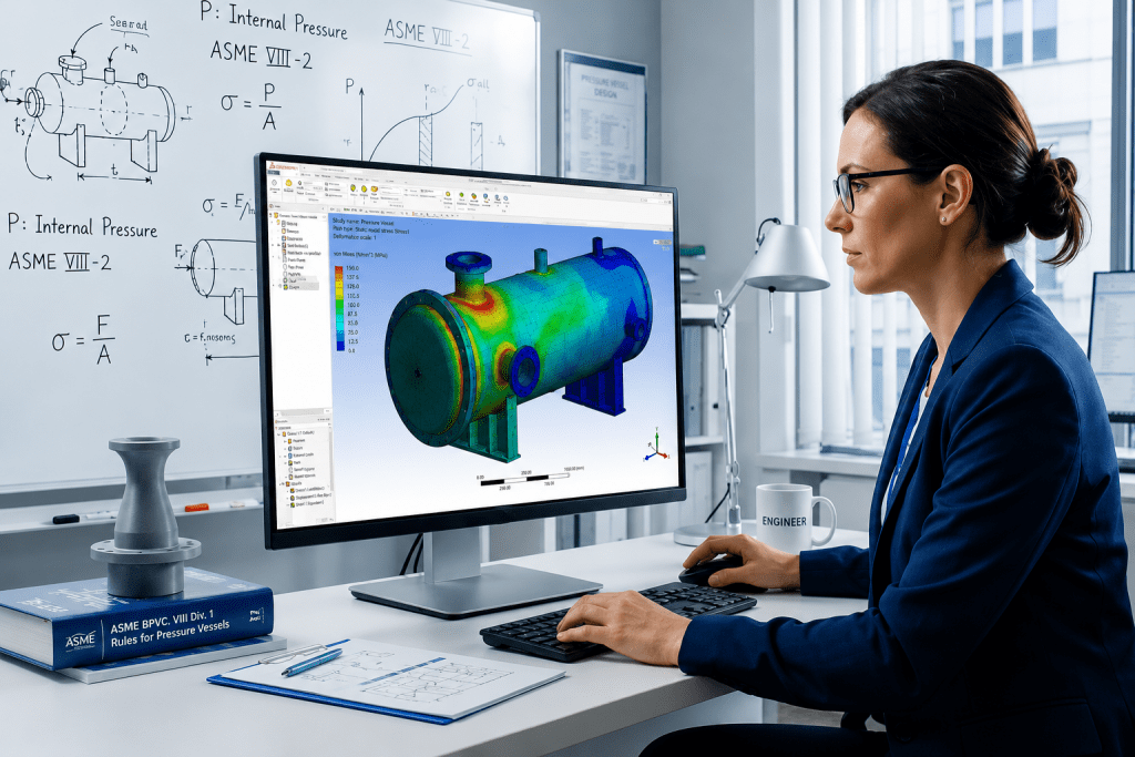
FEA in Pressure Vessel Design: Moving Beyond Design by Rule The global standard method for pressure vessel design has been the “Design-by-Rule” (DBR) methodology governed by popular Boiler and Pressure Vessel Codes like ASME Section VIII, Division 1, AD 2000, PD 5500, EN13445 among others. Design by Rule (DBR) relies on established formulas and safety margins to size components like cylinders, heads, and nozzles. However, these rules only work if you assume the equipment is symmetrical and the loads are simple enough to be conservatively analysed by formula-based methods. The equipment takes physical shape to meet these process demands, the resulting geometry often outgrows the simple mold of established rules in the Code. A vessel’s initial sizing is driven by the process engineer (They dictate exactly what the system needs to function). When a design falls outside the validated scope of standard rules, every major global code provides an “Alternative Design” provision, most famously recognized as ASME Section VIII Division 1’s Paragraph U-2(g) but equally embedded in the core principles of EN 13445, PD 5500, and AD 2000. As, the Code invokes Alternate analysis requirement clause. This clause essentially says if the book doesn’t cover your geometry, you should mathematically prove the design is safe. Alternative Design Provisions (ASME U-2(g), EN 13445, PD 5500, AD 2000) It is a common misconception that triggering these clauses mandates an immediate jump to Finite Element Analysis (FEA). These are Alternative Analysis provisions. They dictate that when the standard rulebook is silent, the engineer is to validate the structural integrity using recognized engineering mechanics. This can be achieved through closed-form analytical calculations (first principles), proof testing, the application of complementary international standards, OR when the geometric complexity outpaces manual mathematics advanced numerical methods like FEA. Let’s Explore what are some potential cases Designers and Engineers can come across which will require them to search beyond DBR methods laid out in the respective Code. In day-to-day static and fixed equipment design, we frequently run into scenarios where standard code rules just aren’t enough. Here are a few of the most common, real-world design issues where FEA becomes an absolute necessity. While the terminology in the examples below leans on ASME Section VIII, Division 1, the underlying physics applies across the board. Because every major “Design by Rule” standard (from EN 13445 to PD 5500) relies on the same basic assumptions of symmetry and uniform loading, they all share the exact same blind spots. Common Real-World Design Scenarios Requiring FEA Local Load Analysis of Geometries Outgrowing WRC LimitsWe use WRC 537 / 107 for analysing static reactions on pressure boundaries, some of the following examples are: Nozzle piping loads on shell and shell to nozzle junction lifting lug and tailing lug attachment to shell. Platform clips and pipe support clips to shell Support legs, Support bracket to shell Nozzle to shell / head junction is overstressed We all rely on WRC 107 / 537 and sometimes WRC 297 to determine local stresses in the shell at structural discontinuities such as legs, support lugs and clip attachments. This bulletin does not address rectangular attachments to shells of double-curvature, and these charts have strict geometric limits. If your nozzle is massive compared to the vessel, or if the shell is extremely thin, or if any rectangular attachment like lug, clips, etc., are welded on double curvature components like heads. WRC methods simply do not provide methods to analyse the concerned geometry. In highly loaded junctions such as a central nozzle supporting an agitator assembly. The standard software with WRC 107 / 537 will provide overstress results and cannot calculate the structural stiffeners. To properly analyze this pressure boundary and guarantee the design is safe, a 3D FEA model is the only practical solution. Non-Uniform Tubesheets Standard TEMA and ASME rules for sizing tubesheets rely on one massive assumption: that the plate is uniformly drilled with holes. For tube layouts which are not uniform where tubesheet is perforated for a small region and large part of it is an untubed area, but real-world heat exchangers often require multi-pass flow, which means there is un-tubed metal. These solid strips act like rigid steel beams. When pressure hits the tubesheet, it doesn’t bend evenly; the un-tubed lanes stay stiff while the drilled areas bow outward. Standard formulas cannot calculate this uneven bending, leading to unexpected shear forces that can rip the tube-to-tubesheet welds apart. As analysts, we model the exact, true geometry of the tubesheet, including every solid un-tubed lane and irregular perimeter gap. This allows the simulation to capture the exact bending behavior and locate the high localized stresses where the flexible tubed region meets the rigid un-tubed metal, ensuring the welds will hold under operating pressure. Large Openings, Extreme Aspect Ratios, and Knuckle Nozzles When you introduce unconventional geometries—like massive openings, obround cutouts, offset/tilted nozzles, or nozzles located right on a head knuckle. Per ASME UG-36(a)(1), if the aspect ratio (the long chord divided by the short chord of the opening) exceeds 2.0, the code warns that additional reinforcement is needed to resist complex bending forces. However, ASME provides no elementary formula for how much reinforcement is needed. Because of this, software will simply flag a permanent warning. This warning will never “disappear” just by artificially thickening the repad in the software, because the error is tied to the physical dimensions of the hole, not the thickness of the steel. The Large Nozzle Limit: If the nozzle is massive, Appendix 1-7(b) takes over. But even those advanced rules have a ceiling. If the ratio of the nozzle radius to the vessel radius exceeds 0.7, the software will complete the Appendix 1-7 analysis but immediately flag that the geometry is still too extreme, requiring additional analysis per U-2(g). Fatigue Life and Cyclic loading Pressure vessels aren’t always static. If a vessel undergoes thousands of pressure or temperature cycles over its lifetime (like a batch reactor continuously filling and draining), the metal can eventually crack from fatigue even if
Piping Stress Analysis Services by MECS Engineering Inc.: Accuracy You Can Trust

Piping Stress Analysis Services by MECS Engineering Inc.: Accuracy You Can Trust </h1 > Home / Learning When you walk through a refinery, a chemical plant, or even a power station, you’ll notice miles of pipes running in every direction. These pipes carry steam, water, oil, chemicals, and gases all under pressure, at different temperatures, and often around the clock. Now imagine what would happen if just one of those pipes failed. The cost, the downtime, the safety risks… it could be huge. That’s why Piping Stress Analysis is so important. At MECS Engineering Inc., we take this responsibility seriously. Our team of experts ensures every piping system we work on is safe, reliable, and built to perform under real-world conditions. What Exactly is Piping Stress Analysis? Think of a pipe like a long, flexible straw. When hot liquid flows through it, it expands. When it cools, it contracts. If it bends too far or gets pushed too hard, it can crack. That’s basically what Piping Stress Analysis is all about: understanding how pipes will react to heat, pressure, movement, and weight. Instead of waiting for a problem to happen, engineers run tests and simulations ahead of time to spot weak points and prevent failures. It’s not about making things complicated. It’s about making sure the system works safely today, tomorrow, and years down the line. Why It Really Matters? A lot of people think pipes are just simple metal tubes. But in industries like oil & gas or power generation, they’re the backbone of the whole operation. Here’s why stress analysis is non-negotiable: Safety above all – Nobody wants leaks, bursts, or dangerous accidents. Money saved – Spotting a problem early is far cheaper than dealing with a breakdown later. Smooth operations – Well-designed systems mean fewer interruptions and better performance. Meeting the rules – Industry codes and regulations demand accurate stress analysis. In short, having a skilled stress analysis engineer on the job means peace of mind for everyone involved. The Human Side of a Stress Analysis Engineer Behind every report and calculation, there’s an engineer who cares about getting it right. A stress analysis engineer isn’t just crunching numbers; they’re problem solvers. Here’s what they typically do: Look over the piping layout and spot tricky areas. Run computer simulations to see how the system reacts under pressure and heat. Recommend small but powerful fixes – maybe adding a support, changing a bend, or adjusting materials. Help project managers feel confident their system will hold up when it’s needed most. At MECS Engineering Inc., our engineers are known not just for their technical skills, but also for being approachable and practical. They don’t just hand over a report – they explain the “why” behind it, in plain language. Who Needs Stress Analysis? The truth is, nearly every industry that depends on piping needs it. A few examples: Oil & Gas – Long pipelines under extreme pressure. Chemical Plants – Where leaks can be dangerous and costly. Power Plants – Steam and water lines that never stop running. Pharma & Food – Clean, safe systems that meet strict hygiene standards. Different industries, same goal: making sure the system is reliable. And that always starts with good Stress Analysis. What Makes MECS Engineering Inc. Different? Lots of firms claim they can handle stress analysis. But at MECS Engineering Inc., accuracy is more than a buzzword — it’s our standard. Here’s how we stand out: Real experience – We’ve handled projects in multiple industries and understand their unique challenges. Modern tools – Our software and methods are designed for accuracy. Practical advice – We don’t just give theory; we offer real, usable solutions. Partnership approach – Clients trust us because we listen, explain, and collaborate. We know that every project is different, and we tailor our work to fit exactly what you need. The Benefits of Doing It Right When you choose professionals for Piping Stress Analysis, here’s what you really gain: Less worry about accidents or shutdowns. Systems that run smoother and last longer. Lower repair costs over the years. Confidence that your system meets all standards. It’s about protecting your people, your plant, and your bottom line. Real Examples, Real Value Picture a refinery where heat expansion causes a pipe to push against a wall. Without stress analysis, that pressure could cause a dangerous leak. But with the right adjustments, the system stays safe. Or think of a power plant where pipes carry steam 24/7. Proper analysis means fewer breakdowns, which means more consistent power supply. These aren’t “what-ifs.” They’re real scenarios where Stress Analysis makes all the difference. Why Partner With Us? At MECS Engineering Inc., we don’t just run calculations — we build trust. We make sure you know your piping system is ready to handle whatever comes its way. Our team blends technical expertise with a human touch. We’re approachable, reliable, and always focused on delivering solutions that work in the real world. Final Thoughts Piping might not always get the spotlight, but without it, industries would grind to a halt. That’s why Piping Stress Analysis is so important. It keeps systems safe, efficient, and reliable. With the help of a skilled stress analysis engineer, companies can avoid costly surprises and keep things running smoothly. And with MECS Engineering Inc., you can count on accuracy, expertise, and a partner who truly cares about your success.
Professional Engineering Consultants For Innovative Solutions: MECS Engineering Inc.

Professional Engineering Consultants For Innovative Solutions: MECS Engineering Inc. Home / Learning If you’ve ever managed a big project, you’ll know one thing—something always comes up. A design snag, a compliance hurdle, a system that just won’t perform the way it should. That’s when having professional engineering consultants on your side makes all the difference. And in my experience, firms like MECS Engineering Inc. don’t just show up with technical drawings and calculations—they bring solutions you can actually use. Why Companies Rely on Engineering Consultants? Let’s be honest. Not every business has the time—or budget—to keep full-time specialists for every type of project. Sometimes you just need the right expertise, right now. That’s where consultants step in. They help you: Save money by avoiding trial-and-error fixes. Speed up timelines with proven processes. Bring in fresh ideas you might not have thought of. Reduce risks before they snowball into bigger issues. I once worked with a client who was struggling with a bottleneck in their production line. Their team had been going in circles for months. When they finally called in consultants, the problem was solved in a week. That’s the kind of value experts bring. What Sets MECS Engineering Inc. Apart So why MECS? Because they’re not just about ticking boxes. They take the time to understand your goals, then tailor solutions that make sense both technically and practically. A Few Areas They Excel In, Structural engineering for safe, lasting builds. Mechanical systems designed to improve performance and cut downtime. Project management that keeps work on track and budgets under control. Sustainable solutions to meet today’s environmental standards. For example, MECS recently helped a client in the energy sector modernize outdated infrastructure. Not only did they fix compliance issues, but the upgrades also shaved off operating costs—something the client hadn’t even considered possible. The Real Value of Professional Consultants Hiring engineering consultants isn’t just about filling knowledge gaps. It’s about perspective. Here’s what you gain when you work with teams like MECS: An outside view: Sometimes you’re too close to a problem to see it clearly. Custom solutions: Not cookie-cutter fixes, but tailored strategies. Flexibility: Bring in expertise when you need it—no long-term overhead. Less risk: Problems get spotted early, before they drain time and money. That outside perspective, especially, is often underestimated. It’s like having someone look at your messy desk and instantly knowing where everything should go. Tips for Working with Consultants If you’re considering hiring a firm like MECS, a few best practices can make the collaboration even smoother: Be clear about your scope: The more defined your goals, the faster progress happens. Stay communicative: Regular updates keep everyone on the same page. Use project tools: Even something as simple as shared dashboards saves headaches. Ask about case studies: Past successes give you confidence in their approach. At the end of the day, the best results come when you treat consultants as an extension of your team, not outsiders. Why MECS Is a Trusted Partner Clients stick with MECS because of how they work—not just what they deliver. They listen. They ask questions that sometimes you hadn’t thought of. And they make sure solutions don’t just look good on paper but actually hold up in the real world. Whether it’s a mid-sized construction project or a massive industrial upgrade, they bring that mix of technical skill and practical sense that saves clients both stress and money. Final Thoughts Choosing the right professional engineering consultants can mean the difference between constant firefighting and smooth, successful projects. With their track record of innovation and client-focused approach, MECS Engineering Inc. has proven they’re a reliable partner for businesses that can’t afford to get it wrong. If you’ve been putting off that tricky project because it feels too complex, maybe it’s time to see what experts like MECS can do for you.
How MECS Engineering Leads in Pipe Stress Analysis and 3D Piping Design
How MECS Engineering Leads in Pipe Stress Analysis and 3D Piping Design Home / Learning In complex engineering projects across Canada, the USA, and beyond, precision and regulatory compliance are non-negotiable. That’s why MECS Engineering is a trusted partner for high-quality pipe stress analysis and 3D piping modeling services. Backed by a team of Professional Engineers licensed in multiple Canadian provinces and several U.S. states, and with deep experience in P.Eng. / P.E. certification and CRN registration, MECS delivers reliable, compliant, and efficient engineering solutions tailored to the demands of modern industry. Expertise That Delivers Results : MECS as Professional Engineering Consultants MECS Engineering brings together a highly experienced team of Professional Engineers specializing in industrial engineering services. Every project we undertake is led by licensed professionals with P.Eng. (Canada) or P.E. (USA) credentials, ensuring full compliance, accountability, and technical integrity. Our team delivers tailored engineering solutions across a range of industries, including oil & gas, hydrogen, renewables, chemical processing, water treatment, and industrial utilities. With a deep understanding of code compliance and real-world constraints, we provide practical, efficient, and scalable designs to meet your project’s unique needs. Why Pipe Stress Analysis is Critical in Engineering Projects Across Canada, the USA, and Beyond Figuring out pipe stress is super important for making sure piping systems are safe and work well. Whether for refineries, power plants, chemical facilities, or hydrogen infrastructure, properly accounting for pressure, temperature, seismic, and mechanical loads is essential to avoid failures, downtime, and costly redesigns. At MECS Engineering, we perform high-quality pipe stress analysis using industry-standard software such as CAESAR II and AutoPIPE. Our engineers check stress, movement, support designs, and nozzle loads to make sure everything meets requirements and lasts a long time. We design and validate systems to meet ASME B31.1, B31.3, B31.5, and other relevant codes, and provide P.Eng. certification (Canada) and P.E. stamping (USA) as required by local jurisdictions or client specifications. Whether you need support in Ontario, Alberta, Texas, or internationally, MECS Engineering provides reliable, code-compliant, and professionally certified pipe stress analysis services tailored to your project. In-depth 3D Piping Modeling Services From Design to commissioning, MECS Engineering delivers intelligent 3D piping models that enhance visualization, reduce design errors, and streamline fabrication workflows. The models support clash detection, material takeoffs, and accurate support layouts, enabling smoother integration across disciplines. All 3D models are developed in accordance with the project-specific requirements, supporting faster regulatory reviews, clearer communication with stakeholders, and more efficient implementation in the field. CRN Certification and Regulatory Compliance MECS has extensive experience in CRN Number applications and Canadian Registration Number compliance for pressure vessels, piping systems, and fittings across all provinces and territories in Canada. We manage the entire CRN process—from preparing code-compliant drawings and calculations to handling submissions, regulator coordination, and revisions—ensuring a faster, smoother approval process. Whether you require P.Eng. stamping (Canada) or P.E. certification (USA), MECS delivers professional engineering services that meet provincial and territorial compliance standards, giving you confidence in every step of your project. Canada’s Trusted Partner Across the Piping Industry From Alberta to Ontario, MECS Engineering is recognized for delivering high-quality, code-compliant solutions for piping systems across Canada and beyond. We support EPC firms, fabricators, and plant owners with comprehensive engineering services—including design documentation, and P.Eng. certification—tailored to meet both project requirements and regulatory demands. Our diverse clientele spans industries such as oil & gas, chemical, hydrogen, power generation, and water treatment—each requiring the precision, reliability, and regulatory expertise that MECS is known for. What Defines MECS Engineering Deep domain expertise backed by Certified Professional Engineering Consultants End-to-end support for CRN (Canadian Registration Number) applications Turnkey solutions for pipe stress analysis across various industries High-precision 3D piping modeling for design clarity and constructability Projects professionally certified with P.Eng. stamps (Canada) or P.E. stamps (USA) In-depth knowledge of Canadian piping codes and standards Priority support for expedited CRN submissions and regulator follow-ups If you’re launching a new piping project or require professional assistance with stress analysis, CRN registration, or 3D modeling, MECS Engineering is your go-to partner. Contact us today for certified engineering services that meet Canadian standards and consistently exceed expectations.
Pipe Stress Analysis Explained: What It Is and How It’s Done

Pipe Stress Analysis Explained: What It Is and How It’s Done Home / Learning Pipe stress analysis is a critical engineering process used to ensure that piping systems can withstand internal and external forces without failure. At MECS Engineering Inc., our team of experienced stress analysis engineers provides reliable piping stress analysis services backed by industry-recognized certifications such as P.Eng. Certification, P.Eng. Stamping, and P.E. Certification. What Is Pipe Stress Analysis? Pipe stress analysis is the process of evaluating stresses, displacements, and loads in piping systems. It helps determine whether the system can handle thermal expansion, pressure, dead weight, and other external loads. Proper analysis ensures compliance with codes like ASME B31.1 and B31.3. Why Is Piping Stress Analysis Important? Performing accurate piping stress analysis is essential for: Preventing pipe failures or leaks Ensuring long-term system durability Meeting safety and code requirements Achieving certification and regulatory approval At MECS Engineering, we understand that both piping flexibility analysis and load assessments play a key role in the design and maintenance of safe systems. Steps to Perform Pipe Stress Analysis Our expert stress analysis engineers follow a structured process: 1. System Modeling Create a detailed 3D model of the piping system using software like CAESAR II or AutoPIPE. 2. Input Data Collection Include: Material specifications Operating pressure and temperature Pipe layout and support details External loads (e.g., wind, seismic) 3. Load Case Definitions Define load combinations (sustained, thermal, occasional) based on design codes. 4. Flexibility and Stress Check Run piping flexibility analysis to assess displacement, anchor loads, and stresses. 5. Code Compliance Verification Check results against standards such as ASME B31.1 and 31.3 to ensure the system passes stress limits. 6. Report and Certification Provide a detailed report along with P.Eng. Stamping, P.Eng. Certification, or P.E. Certification depending on regional requirements Tools We Use for Stress Analysis We utilize industry-leading tools such as: CAESAR II Rohr2 AutoPIPE These tools help simulate complex loading scenarios and validate the mechanical integrity of your piping system. Common Issues Identified During Stress Analysis Overstressed pipe sections Insufficient support spacing Excessive nozzle loads on equipment Thermal expansion causing misalignment These issues can be resolved by making layout changes, adding guides or anchors, and improving pipe flexibility. Industries That Rely on Stress Analysis Our piping stress analysis services are trusted across multiple sectors: Oil & Gas Power Generation Chemical Processing Food & Beverage Water Treatment Each project receives oversight by a certified stress analysis engineer and, where applicable, a stamped design with P.Eng. Certification or P.E. Certification. Why Choose MECS Engineering Inc. for Pipe Stress Analysis? Certified stress analysis engineers Detailed report with Eng. Stamping Experience in both greenfield and brownfield projects Advanced piping flexibility analysis Timely delivery and code-compliant results Summary: Key Benefits of Pipe Stress Analysis Ensures structural safety and performance Detects design flaws early Aids in code compliance and certification Increases equipment and system longevity Reduces risk of costly shutdowns Contact MECS Engineering today for professional analysis, full P.Eng. Certification, and precise piping flexibility analysis for your project.
Top 7 Mistakes to Avoid in Civil and Structure Design Projects

Top 7 Mistakes to Avoid in Civil and Structure Design Projects </h1 > Home / Learning Avoiding critical errors in civil and structure design projects is essential for ensuring safe, efficient, and cost-effective construction. From ignoring site conditions to miscommunication between teams, these mistakes can lead to costly delays and structural failures. In this blog, we will explore the top 7 mistakes to avoid in civil and structure design projects to help engineers, architects, and project managers achieve successful outcomes. 1. Inadequate Site Analysis and Soil Investigation A proper understanding of the site’s geology is the foundation of civil design. Ignoring soil type, bearing capacity, and water table data Overlooking environmental and topographical constraints Relying solely on outdated survey reports Tip: Always conduct geotechnical investigations before beginning the structural design phase. 2. Poor Coordination Between Civil and Structural Teams One of the biggest design risks is poor communication between stakeholders. Lack of integration between architectural, MEP, and structural teams Design conflicts that arise due to missing coordination Delayed revisions increasing project timelines Tip: Adopt BIM tools and regular design reviews to maintain synergy. 3. Underestimating Load Calculations Accurate load calculations are vital to prevent structural failures. Incorrect estimation of dead and live loads Ignoring seismic and wind load effects Inadequate allowance for future expansions Tip: Follow local and international codes like IS 456 or ACI 318 for standard load considerations. 4. Non-Compliance with Local Building Codes Legal issues and penalties can arise from code violations. Designing without considering municipal regulations Not updating plans with the latest code revisions Using obsolete design software that misses compliance checks Tip: Always cross-check designs with applicable civil and structure design regulations. 5. Overlooking Constructability and Site Constraints Practical challenges at the construction site are often ignored during design. Designs that cannot be practically executed onsite Ignoring crane, equipment, or workforce limitations Complex structural elements that delay execution Tip: Involve construction teams during the design phase for better feasibility. 6. Ignoring Sustainability and Material Optimization Overdesigning structures increases costs and environmental impact. Using unnecessarily large cross-sections or materials Not exploring high-performance or eco-friendly materials Excessive concrete usage increasing carbon footprint Tip: Optimize structures with value engineering and sustainable material selection. 7. Lack of Peer Review and Design Validation Skipping quality checks can result in major engineering errors. Designs not peer-reviewed by qualified professionals Absence of stress analysis or FEA where applicable No simulation of load conditions or serviceability Tip: Schedule independent design audits and simulations for large or critical structures. Key Takeaways: What to Remember Always start with a detailed site and soil investigation. Encourage interdisciplinary coordination for integrated design. Prioritize accurate load analysis using verified standards. Comply with building codes to avoid legal setbacks. Consider site constraints and construction feasibility early. Focus on sustainability and resource efficiency. Conduct peer reviews and simulations to validate designs. Avoid Mistakes, Build with Confidence – Partner with MECS Engineering At MECS Engineering, we specialize in civil and structure design solutions tailored to your project needs. Our team ensures full compliance, precision, and performance — from initial surveys to final design validation. Contact us today to schedule a consultation or learn more about how we can help your next project succeed without costly design errors.
How to Perform Stress Analysis in Pressure Vessel Design

How to Perform Stress Analysis in Pressure Vessel DesignLearning Home / Learning In the world of mechanical and process engineering, pressure vessels are essential components used to store and transport pressurized gases and liquids. However, these vessels are constantly subjected to internal pressure, temperature changes, external forces, and more. This is where stress analysis in pressure vessel design becomes crucial—it ensures safety, compliance, and long-term reliability. Why Stress Analysis Is Essential? Pressure vessels operate under harsh and demanding conditions. Without proper stress analysis: Catastrophic failures can occur. Equipment lifespan is reduced. Safety codes and certifications may not be met. Downtime and liability risks increase. That’s why industries such as oil & gas, petrochemical, food processing, and pharmaceuticals rely heavily on accurate stress evaluation and code compliance during the design phase. Key Types of Stress in Pressure Vessels Understanding different stress types helps engineers design vessels that perform reliably. Here are the primary categories: Hoop Stress (Circumferential Stress) Acts tangentially around the vessel’s circumference. Most critical in cylindrical shells. Formula: σₕ = (P × r) / t Longitudinal Stress Acts along the length of the vessel. Generally half of the hoop stress. Formula: σₗ = (P × r) / (2t) Radial Stress Occurs across the wall thickness of the vessel. Minor compared to hoop and longitudinal stress but important in thick-walled vessels. Thermal Stress Caused by temperature differences across the vessel. Can lead to fatigue if not considered in design. Localized or Discontinuity Stress Present near nozzles, welds, supports, and openings. Requires detailed modeling for accurate analysis. Three Main Methods of Stress Analysis 1. Analytical Calculations Based on classical mechanics. Suitable for simple geometries (cylindrical/spherical). Uses thin-wall or thick-wall assumptions. Quick but limited in scope. 2. Code-Based Calculations (ASME, PED, IS Codes) Provide formulas and design criteria based on operating conditions. ASME Section VIII Division 1 & 2 are widely used standards. Ensure safety margins and legal compliance. Used for certification and CRN approvals. 3. Finite Element Analysis (FEA) Advanced computational technique. Ideal for complex geometries and loading conditions. Simulates real-world scenarios including thermal gradients, nozzle loads, and seismic effects. Provides precise insight into stress concentrations and failure points. Step-by-Step: Performing Stress Analysis with FEA Modern design relies heavily on FEA-based stress analysis. Here’s how engineers typically approach it: Step 1: Model the Geometry Start with 3D CAD of the vessel including nozzles, flanges, stiffeners. Simplify wherever possible without compromising accuracy. Step 2: Assign Material Properties Choose materials based on ASME code tables. Include yield strength, thermal conductivity, and Poisson’s ratio. Step 3: Apply Loads & Boundary Conditions Internal/external pressure Dead weight and supports Thermal loads and wind/seismic forces Fixed, pinned, or sliding constraints Step 4: Mesh the Model Create finite elements using a structured or unstructured mesh. Refine mesh near areas of high stress (nozzles, junctions). Step 5: Run Simulation Use solvers (linear static, thermal, or buckling). Observe displacement, von Mises stress, principal stresses. Step 6: Validate and Interpret Results Compare stress values to code-allowable limits. Look for hot spots or discontinuity failures. Evaluate fatigue life if cyclic loading is present. Step 7: Document and Optimize Generate engineering reports with visuals. Recommend reinforcements, thickness changes, or support adjustments. Popular FEA Tools Used for Pressure Vessel Design ANSYS Mechanical SolidWorks Simulation Autodesk Inventor Nastran Abaqus PV Elite (for code-based stress checks) These tools allow integration with design codes and help simulate not just static loading, but also dynamic, thermal, and fatigue conditions. Common Industries Where Stress Analysis is Critical Oil & Gas: Pressure separators, flare stacks, storage tanks Petrochemical Plants: Heat exchangers, reactors Pharmaceutical: Sterile vessels, jacketed tanks Food & Beverage: Steam kettles, CIP vessels Power Plants: Steam drums, boilers, condensers Best Practices for Pressure Vessel Stress Analysis Always use the latest ASME/PED/IS codes. Validate Finite Element Analysis (FEA) models with hand calculations.Use proper mesh convergence studies. Document boundary conditions and assumptions. Include thermal and fatigue analysis in high-temperature applications. Get Expert Help with Your Pressure Vessel Design Performing accurate stress analysis is a technical and regulatory requirement—and it demands experience, certification, and precision. At MECS Engineering, we specialize in: Pressure vessel design and certification FEA simulation for static and thermal stress CRN registration for Canada Code compliance (ASME, CSA, PED) Let our licensed engineers (P.Eng) help you design vessels that are safe, efficient, and fully certified.
Analyzing Seismic Loads in Piping Systems for Earthquake-Prone Areas

Analyzing Seismic Loads in Piping Systems for Earthquake-Prone Areas Home / Learning In earthquake-prone regions, designing resilient piping systems is essential to ensure public safety and protect infrastructure. Seismic loads introduce unique challenges, including dynamic forces from ground movement and structural interactions between pipelines and their surroundings. A well-engineered piping system must withstand seismic stresses, maintaining functionality during and after seismic events. This article delves into the critical aspects of seismic design for piping systems, covering the methodologies, analytical techniques, and practical benefits of incorporating seismic resilience into pipeline engineering. Why Seismic Design Matters in Piping Systems Piping systems in earthquake-prone regions are vulnerable to damage due to seismic forces. The impact ranges from minor deformation to catastrophic failure, leading to hazardous leaks, equipment damage, and operational shutdowns. This risk is particularly high in safety-critical industries such as nuclear power, chemical processing, and oil and gas.To mitigate these risks, engineers use specialized seismic analysis and design methodologies to predict and accommodate the effects of ground movements. These designs factor in: Seismic hazards specific to the region. Piping system geometry and material properties. Interaction with supporting structures. Key Factors in Seismic Design Seismic analysis is influenced by several critical factors, including the natural frequencies, restraint configuration, and response spectra. Here’s an in-depth look: Piping Geometry and Restraint ConfigurationThe natural frequency of a piping system is dictated by its geometry and restraint layout. By strategically altering these elements, engineers can “tune” the system to avoid resonance and reduce seismic loads. Response SpectraResponse spectra measure how a structure, such as a building or support, amplifies ground vibrations during an earthquake. Understanding this amplification is critical for assessing the piping system’s response and designing appropriate mitigation measures. Earthquake History and Regional SeismicitySeismic design starts with an assessment of earthquake potential, based on historical seismic data. This includes analyzing previous earthquakes’ intensity, frequency, and impact, combined with geological and geotechnical studies. Methods for Seismic Analysis and Design Seismic analysis employs both static and dynamic methods, each suited to specific scenarios. The five primary techniques are: Uniform Building Code (UBC) Analysis: The UBC provides a framework for estimating seismic loads based on regional damage potential. Earthquake zones are classified as 0 (minimal risk) to 3 (high risk), and seismic coefficients (Z) are assigned accordingly. The design load is calculated using the formula: g=ZKCT Where: g = static equivalent g-factor to use for seismic design, multiples of gravity Z = seismic coefficient based on earthquake zone, equal to 0.0 for Zone 0,0.25 or Zone 1, 0.5 for Zone 2, and 1.0 for Zone 3 K = structure type constant, ranging from 0.67 to 3.0, dimensionless C = 0.05/T^(1/3), but not greater than 0.1 T = fundamental period (inverse of frequency) of structure, sec This method converts dynamic seismic forces into an equivalent static load, simplifying analysis for routine design applications. Nuclear Seismic Design: Nuclear facilities require stringent seismic designs due to the critical nature of their operations. This involves advanced modeling techniques and adherence to strict regulatory codes. The piping in these facilities undergoes comprehensive stress evaluations, ensuring it meets allowable limits even during extreme seismic events. Time History Analysis: Time history analysis uses earthquake records to simulate seismic effects on piping systems. This method involves: Plotting ground motion data (displacement, velocity, acceleration) over time for three spatial directions. Applying these data to a dynamic model of the piping system. The analysis provides detailed insights into stress, displacement, and support loads at each time step during an earthquake. Although highly accurate, this method is computationally intensive and expensive, making it ideal for critical systems in high-risk regions. Modal Analysis Using Response Spectra: Modal analysis simplifies dynamic analysis by breaking a piping system into individual vibration modes. Engineers calculate the response of each mode to seismic input and combine these to determine the total system response. Key equations include: Where, This method is cost-effective compared to time history analysis and widely used for complex piping systems. When the applied acceleration is removed from an undamped oscillator (a=0,C=0), the system continues to vibrate at its undamped natural frequency (ωnomega_nωn). This frequency is critical in assessing the dynamic response of the piping system. Applying a vibratory motion to the system can result in higher accelerations on the mass than those input at the base. This outcome depends on the interaction of velocity and displacement at specific moments during the seismic event. By examining the amplification factor, the shape of the response spectra becomes clear: Flexible Range: When the oscillator’s natural frequency is much smaller than the forcing frequency, the amplification factor approaches zero. Resonant Range: As the oscillator frequency nears the forcing frequency, the amplification factor increases significantly, resulting in two distinct peaks. Rigid Range: When the oscillator frequency is much greater than the forcing frequency, the amplification factor approaches 1.0. The acceleration matches the imposed motions, termed as zero-period acceleration. These ranges dictate the dynamic behavior of the system and highlight how seismic forces amplify or attenuate depending on frequency relationships. The total seismic response of the piping system is determined by summing the responses of its individual vibration modes. These responses depend on the natural frequencies of the system, which are influenced by its geometry and restraint configuration. By adjusting these parameters, engineers can “tune” the system to modify its natural frequencies, thereby reducing its seismic response and associated stresses. The response spectra effectively represent the interaction between the building and the piping system during an earthquake. Natural frequencies and mode shapes of the piping system are typically calculated using a lumped-mass model in computational analysis, which employs an eigenvalue-eigenvector algorithm. Static Analysis: Static analysis is employed when detailed dynamic modeling is unnecessary. It approximates seismic forces using a simplified approach. For example: Using response spectra data, engineers identify the acceleration corresponding to the system’s fundamental frequency. Multiplying this acceleration by the piping’s linear weight determines the static seismic load. This conservative method is suitable for less critical applications or systems where response spectra data
Understanding Third-Party Verification: Why It’s Essential in Engineering Projects

Understanding Third-Party Verification: Why It’s Essential in Engineering Projects Home / Learning With the engineering projects becoming more complex, third-party verification has emerged as a cornerstone for ensuring quality, regulatory adherence, and reliability. This independent assessment is essential for enhancing project integrity and transparency, where objectivity is important to meeting high standards. It covers a spectrum of critical activities—such as inspections, document reviews, and quality audits—that verify each project component meets precise industry benchmarks. Here, we explore the importance of third-party verification, its detailed processes, and the substantial benefits it brings to engineering projects. What is Third-Party Verification? Third-party verification is a process in which an independent party assesses various project facets—such as design specifications, material properties, regulatory compliance, constructability, operability, maintainability, and safety (COMS) aspects – to ensure adherence to industry standards. The neutrality of third-party verifiers eliminates potential conflicts of interest ensuring a fair and unbiased evaluation. MECS Engineering offers expert third-party verification services across industries such as Process, Power (Nuclear and Fossil), Co-Generation, Oil and Gas, Refineries, Chemical and Petrochemical, and Pharmaceutical Facilities. Key Activities in Third-Party Inspection at MECS Engineering: Third-party verification at MECS Engineering typically involves the following activities: Documentation Review: Ensuring design documents and specifications meet project and industry standards. Code Compliance Verification: Confirming adherence to codes such as ASME for engineering and safety standards. Regulatory Compliance: Verifying that designs align with applicable regulations to ensure project viability. Safety and Operability Assessment: Reviewing designs for safety and operational effectiveness. Comprehensive Reporting: Providing a detailed report with compliance findings and recommendations. Why Third-Party Verification Matters Objective Evaluation: Our independent verification ensures unbiased evaluation, free from internal project pressures. This impartiality is especially important for assessing components where project teams may have vested interests, such as financial targets or project deadlines. Compliance Assurance: Engineering projects must comply with various standards and codes. Our team at MECS Engineering possess in-depth regulatory knowledge, providing a rigorous assessment to ensure that your projects are fully compliant with local and international regulatory requirements, Risk Mitigation: Early identification of potential issues is crucial for managing risk. By detecting discrepancies and recommending improvements, our team helps in addressing risks proactively, contributing to seamless project execution. Technical Proficiency: Our team of experts, ensures that your project components are assessed by professionals knowledgeable industry leader in specific technical areas, thereby upholding project standards. In conclusion, third-party verification might sometimes appear as an extra step, but it’s essential for ensuring project quality, compliance, and long-term reliability. By providing an objective evaluation, MECS Engineering safeguards projects against oversights and elevates them to meet stringent industry standards. This independent verification reinforces project success, builds trust, and minimizes risks that could compromise quality or lead to costly rework. To discuss how MECS Engineering can add value to your projects through third-party verification, contact us at www.mecsengineering.com
